Hyundai Palisade (LX2): Panorama Sunroof / Components and components location
| Component Location |
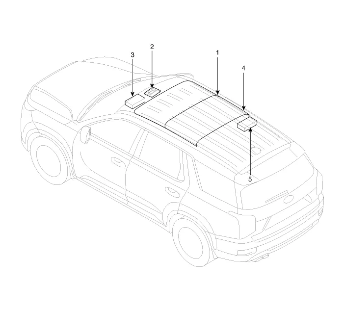
| 1. Panorama sunroof 2. Panorama sunroof switch 3. Panorama sunroof motor & controller |
4. Roller blind 5. Roller blind motor |
Circuit Diagram Sunroof Roller blind Connector Pin Information Sunroof No Wire harness connector Panorama motor 1 Ground Ground 2 Open switch Open switch (SIG A) 3 ICU Enable ICU Enable 4 Tilt up switch Tilt up switch 5 Close switch LIN Bus 6 Battery (+) Battery (+) 7 Open alarm switch Open alarm switch 8 Vehicle speed Vehicle speed 9 - Config pin 10 - Close switch (SIG B) Roller blind No Wire harness connector Panorama motor 1 Ground Ground 2 Open switch Open switch (SIG A) 3 ICU Enable ICU Enable 4 - - 5 Close switch LIN Bus 6 Battery (+) Battery (+) 7 - - 8 - - 9 - Config pin 10 - Close switch (SIG B)
Other information:
Hyundai Palisade (LX2) 2020-2026 Service Manual: Temperature Control Actuator
Description and operation Description The heater unit includes mode control actuator and temperature control actuator. The temperature control actuator is located at the heater unit. It regulates the temperature by the procedure as follows.
Hyundai Palisade (LX2) 2020-2026 Service Manual: Surround View Monitor (SVM) Unit
Components and components location Components No Connector A 1 ACC 2 LED 3 EXT Ground 4 Y Shield 5 - 6 C-CAN Low 7
Categories
- Manuals Home
- Hyundai Palisade Owners Manual
- Hyundai Palisade Service Manual
- Electrochromatic Mirror (ECM) with homelink system
- Components and components location
- Rain Sensor
- New on site
- Most important about car
