
Hyundai Palisade (LX2): Fuses And Relays / Components and components location
Hyundai Palisade (LX2) 2020-2026 Service Manual / Body Electrical System / Fuses And Relays / Components and components location
| Component Location |
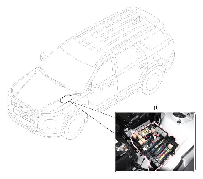
| 1. Engine room relay box |
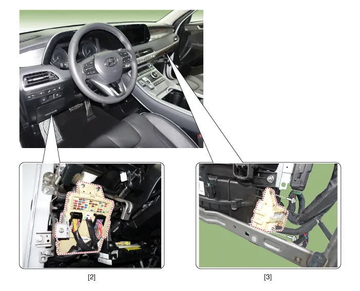
| 2. ICU Junction block |
3. ICM relay box |
Repair procedures Inspection 1. Disconnect the negative (-) battery terminal. 2. Pull out the relay from the engine compartment relay box.
Other information:
Hyundai Palisade (LX2) 2020-2026 Service Manual: Wireless Power Charging Unit
Components and positions Components Circuit diagram Circuit Diagram Repair procedures Removal Handling wireless charging system parts by wet hands may cause electric shock.
Hyundai Palisade (LX2) 2020-2026 Service Manual: Power Mosfet (DATC)
Repair procedures Inspection 1. Turn the ignition switch ON. 2. Manually operate the control switch and measure the voltage of the blower motor. 3. Select the control switch to raise the voltage until high speed.
Categories
- Manuals Home
- Hyundai Palisade Owners Manual
- Hyundai Palisade Service Manual
- Repair procedures
- Electronic Child Safety Lock System
- Scheduled maintenance services
- New on site
- Most important about car

Copyright В© 2026 www.hpalisadelx.com - 0.0099