Hyundai Palisade (LX2): Fuses And Relays / Relay Box (Engine Compartment)
Repair procedures
| Inspection |
| 1. |
Disconnect the negative (-) battery terminal.
|
| 2. |
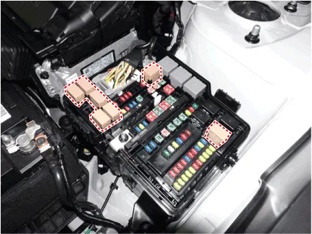
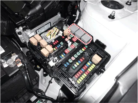
Pull out the relay from the engine compartment relay box.
|
|

| 1. |
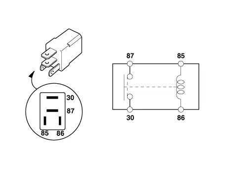
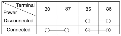
There should be continuity between the No.30 and No.87 terminals when
power and ground are connected to the No.85 and No.86 terminals.
|
| 2. |
There should be no continuity between the No.30 and No.87 terminals
when power is disconnected.
[Engine room relay box]
|
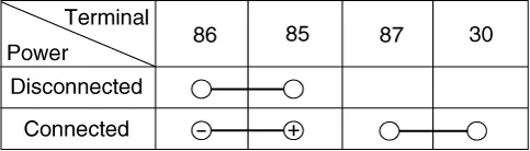
| 1. |
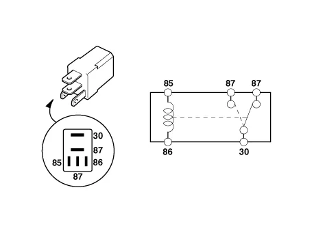
There should be continuity between the No.30 and No.87 terminals when
power and ground are connected to the No.85 and No.86 terminals.
|
| 2. |
There should be continuity between the No.30 and No.87 terminals when
power is disconnected.
|

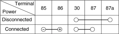
| 1. |
There should be continuity between the No.30 and No.87 terminals when
power and ground are connected to the No.85 and No.86 terminals.
|
| 2. |
There should be no continuity between the No.30 and No.87 terminals
when power is disconnected.
|

| 1. |
Disconnect the negative (-) battery terminal.
|
| 2. |
Push 4 hooks in the engine room relay box out to the arrow direction
and put up the PCB block (A).
|
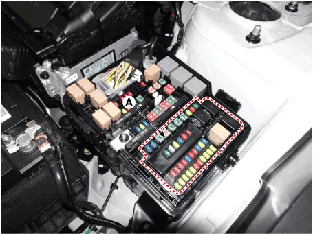
| 3. |
Disconnect the connector and remove the the PCB block (A).
|
| 1. |
Be sure there is no play in the fuse holders, and that the fuses are
held securely.
|
| 2. |
Are the fuse capacities for each circuit correct?
|
| 3. |
Are there any blown fuses?
If a fuse is to be replaced, be sure to use a new fuse of the same capacity.
Always determine why the fuse blew first and completely eliminate the
problem before installing a new fuse.
|

|

Component Location 1. Engine room relay box 2. ICU Junction block 3. ICM relay box
Description and operation Dscription and Operation ICU (Integrated Central Control Unit) ICU (Integrated Central Control Unit) is an integrated model of smart junction block and central gateway.
Other information:
Hyundai Palisade (LX2) 2020-2026 Service Manual: Photo Sensor
Description and operation Description The photo sensor is located at the center of the defrost nozzles. The photo sensor contains a photovoltaic (sensitive to sunlight) diode. The solar radiation received by its light receiving portion, generates an electromotive force in proportion to the amount of radiation received wh
Hyundai Palisade (LX2) 2020-2026 Service Manual: Mode Control Actuator
Description and operation Description The mode control actuator is located at the heater unit. It adjusts the position of the mode door by operating the mode control actuator based on the signal of the A/C control unit. Pressing the mode select switch makes the mode control actuator shift in order of Vent → Bi-Level →
Categories
- Manuals Home
- Hyundai Palisade Owners Manual
- Hyundai Palisade Service Manual
- Scheduled maintenance services
- Resetting the Driver's Seat Memory System
- Automatic Transaxle Fluid (ATF)
- New on site
- Most important about car
