Hyundai Palisade (LX2): Emission Control System / Components and components location
Hyundai Palisade (LX2) 2020-2026 Service Manual / Emission Control System / Components and components location
| Components Location |
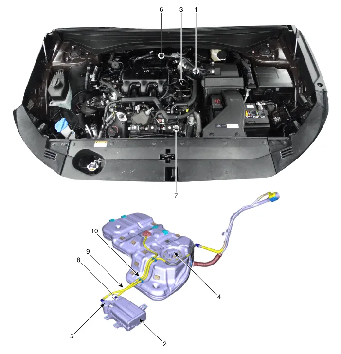
| 1. PCV Valve 2. Canister 3. Purge control solenoid valve (PCSV) 4. Fuel level sensor (FLS) 5. Fuel tank air filter |
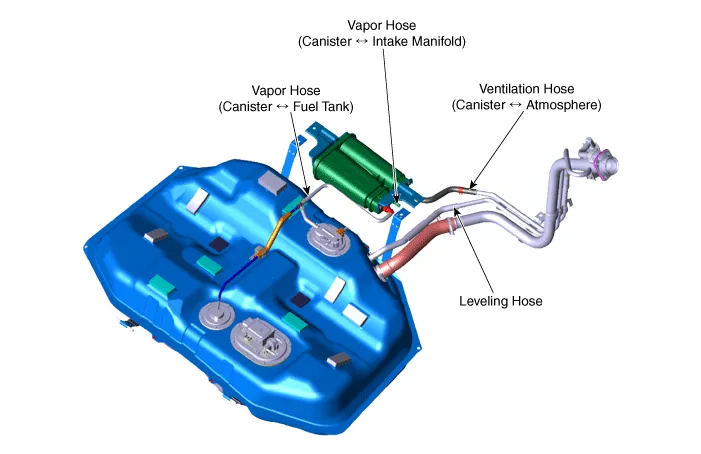
6. Catalytic converter (WCC) 7. Catalytic converter (UCC) 8. Vapor hose (Canister ↔ Intake Manifold ) 9. Vapor Hose (Canister ↔ Fuel Tank) 10. Ventilation hose (Canister ↔ Atmosphere) |
|
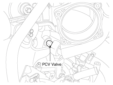
1. PCV valve |
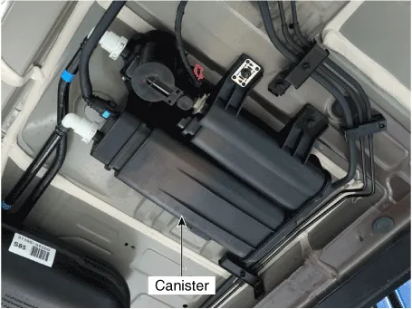
2. Canister |
|
|
|
|
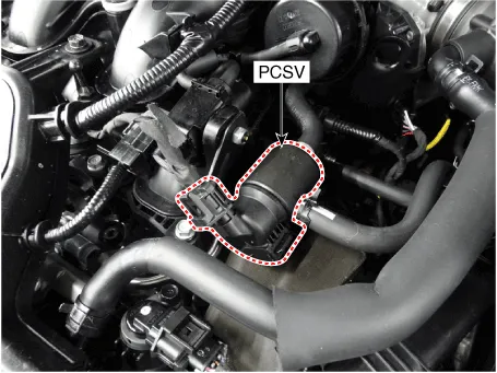
3. Purge Control Solenoid Valve (PCSV) |
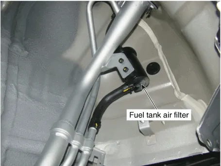
4. Fuel Tank Air Filter |
|
|
|
|
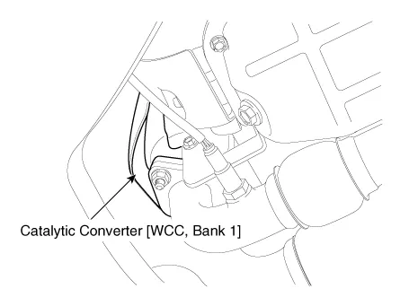
5. Catalytic Converter (WCC, Bank 1) |
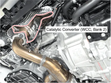
5. Catalytic Converter (WCC, Bank 2) |
|
|
|
|
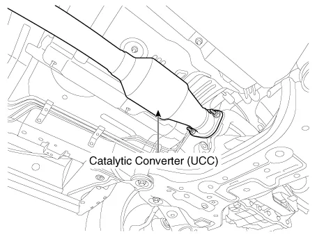
6. Catalytic Converter (UCC) |
|
|
|
|
|
7. Leveling Hose 8. Vapor Hose (Canister ↔ Intake Manifold) 9. Vapor Hose (Canister ↔ Fuel Tank) 10. Ventilation Hose (Canister ↔ Atmosphere) |
|
|
|
|
Schematic Diagram
Other information:
Hyundai Palisade (LX2) 2020-2026 Service Manual: Ambient Temperature Sensor
Description and operation Description The ambient temperature sensor is located at the front of the condenser and detects ambient air temperature. It is a negative type thermistor; resistance will increase with lower temperature, and decrease with higher temperature.
Hyundai Palisade (LX2) 2020-2026 Service Manual: Cruise Control (CC) Switch
Components and components location Components 1. Remote control switch (Audio swtich) 2. Remote control switch (Cruise control switch) Schematic diagrams Circuit Diagram Repair procedures Removal 1.
Categories
- Manuals Home
- Hyundai Palisade Owners Manual
- Hyundai Palisade Service Manual
- Electrochromatic Mirror (ECM) with homelink system
- Resetting the Driver's Seat Memory System
- Rain Sensor
- New on site
- Most important about car

Copyright © 2026 www.hpalisadelx.com - 0.0126