Hyundai Palisade (LX2): Brake System / Brake Pedal
Components and components location
| Components |
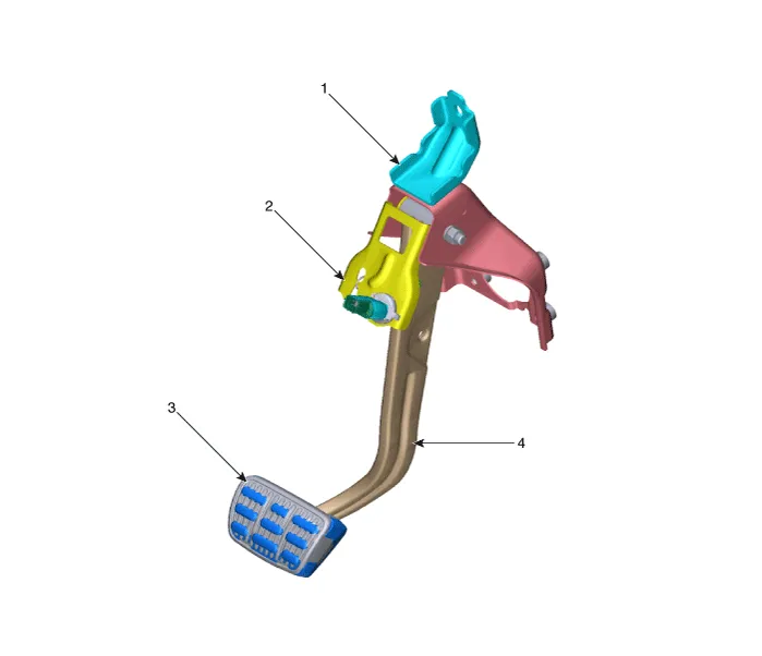
| 1. Brake member assembly 2. Stop lamp switch |
3. Brake pedal arm assembly 4. Brake pedal pad |
Repair procedures
| Removal |
| 1. |
Turn ignition switch OFF and disconnect the negative (-) battery cable.
|
| 2. |
Remove the crash pad lower panel.
(Refer to Body - "Crash Pad Lower Panel")
|
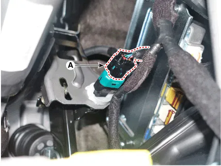
| 3. |
Disconnect the stop lamp switch connector (A).
|
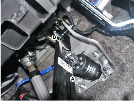
| 4. |
Separate the snap pin (A) and clevis pin (B).
|
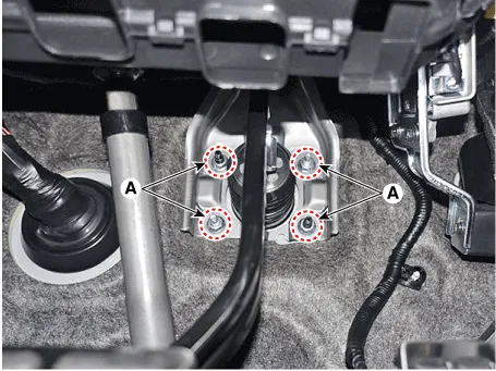
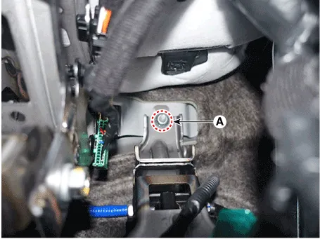
| 5. |
Remove the brake pedal assembly after loosening the mounting nuts (A).
|
| Inspection |
| 1. |
Check the brake pedal for bending or twisting.
|
| 2. |
Check the brake pedal return spring for damage.
|
| 3. |
Check the stop lamp switch.
(Refer to Brake System - "Stop Lamp Switch")
|
| Installation |
| 1. |
To install, reverse the removal procedures.
|

Specifications Specification Fluid Type DOT 3 or DOT 4 Reservoir Quantity (cc) Total A + B + C + D + E + F 460 ± 20 MAX LEVEL A + B + C + D + E 440 ± 20 MIN LEVEL B + C + D + E 165 ± 20 ON LEVEL C + D + E 135 ± 10 PARTIAL LEVEL D Pri : 60 ± 5 D Sec : 50 ± 5 CLUTCH LEVEL F 15 ± 5 Repair procedures Replacement • Be careful not to damage the parts located under the vehicle (floor under cover, fuel filter, fuel tank and canister) when raising the vehicle using the lift.
Components and components location Components 1. Caliper body 2. Pad inner shim 3. Brake pad 4. Pad retainer 5.
Other information:
Hyundai Palisade (LX2) 2020-2026 Service Manual: Repair procedures
Refrigerant System Service Basics (R-134a) Refrigerant Recovery Use only service equipment that is U.L-listed and is certified to meet the requirements of SAE J2210 to remove HFC-134a(R-134a) from the air conditioning system.
Hyundai Palisade (LX2) 2020-2026 Service Manual: Surround View Monitor (SVM) Camera
Components and components location Components [Ultra Optical Camera - RH/LH] [Ultra Optical Camera - Front] [Ultra Optical Camera - Rear] Repair procedures Removal • In case of bad quality or poor
Categories
- Manuals Home
- Hyundai Palisade Owners Manual
- Hyundai Palisade Service Manual
- Rear Heater Unit
- Automatic Transaxle Fluid (ATF)
- Convenient Features of Your Vehicle
- New on site
- Most important about car
