Hyundai Palisade (LX2): AVN System / AVN Head Unit
Components and components location
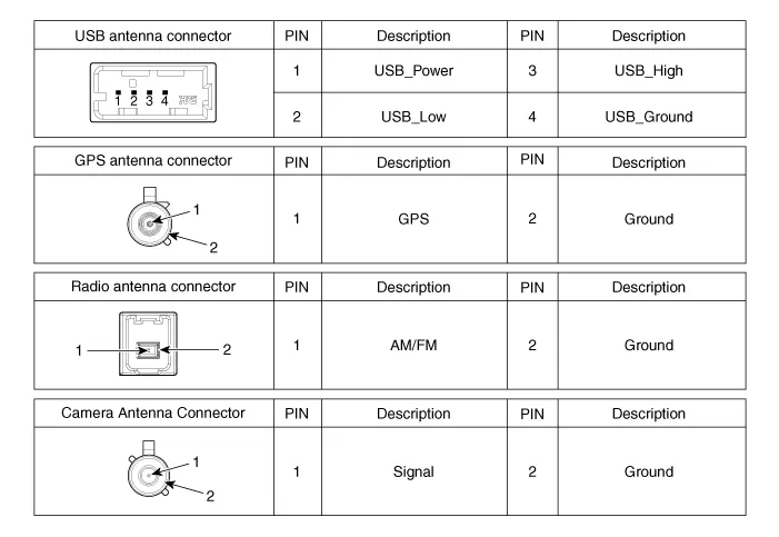
| Components |
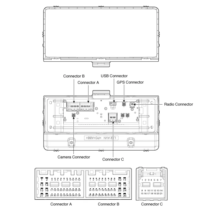
|
No |
Connector A (ExternalAmplifier) |
Connector A (Internal Amplifier) |
Connector B |
Connector C |
|
1 |
- |
Rear door speaker LH (+) |
- |
- |
|
2 |
- |
Rear door speaker LH (-) |
Mic (+) |
I_CAN (High) |
|
3 |
Navigation voice (+) |
- |
- |
- |
|
4 |
External amplifier SPDIF (+) |
- |
- |
- |
|
5 |
Reset |
Reset |
Antenna dummy power |
- |
|
6 |
RVM : Camera Power , SVM : - |
RVM : Camera Power , SVM : - |
Illumination (+) |
- |
|
7 |
RVM : Camera Video , SVM : - |
RVM : Camera Video , SVM : - |
M-CAN (High) |
- |
|
8 |
- |
- |
- |
- |
|
9 |
- |
- |
- |
- |
|
10 |
- |
- |
Battery (+) |
- |
|
11 |
AUX DETECT |
AUX DETECT |
Battery (+) |
- |
|
12 |
Steering wheel remote |
Steering wheel remote |
Ground |
- |
|
13 |
- |
Front door speaker LH (+) |
Ground |
- |
|
14 |
- |
Front door speaker LH (-) |
- |
- |
|
15 |
- |
Front door speaker RH (-) |
Mic (-) |
- |
|
16 |
- |
Front door speaker RH (+) |
- (SVM type:SVM Detect2) |
MTS Key |
|
17 |
Navigation voice (-) |
- |
- |
- |
|
18 |
External amplifier SPDIF (-) |
- |
- |
- |
|
19 |
External amplifier SPDIF (Ground) |
- |
Illumination (-) |
- |
|
20 |
RVM : Camera Power GND , SVM : - |
RVM : Camera Power GND , SVM : - |
M-CAN (Low) |
- |
|
21 |
RVM : Camera Video GND , SVM : - |
RVM : Camera Video GND , SVM : - |
- |
- |
|
22 |
- |
- |
ACC |
|
|
23 |
- |
- |
Keyboard Power |
|
|
24 |
- |
- |
- |
|
|
25 |
- |
- |
- |
|
|
26 |
Steering wheel remote ground |
Steering wheel remote ground |
- |
|
|
27 |
- |
Rear door speaker RH (-) |
- |
|
|
28 |
- |
Rear door speaker RH (+) |
- |
|
|
29 |
- |
- |
- |
|
|
30 |
- |
- |
- |
|
|
31 |
- |
- |
- |
|
|
32 |
SVM DETECT 1 |
SVM DETECT 1 |
- |
|
|
33 |
RVM : Camera Shield GND , SVM : - |
RVM : Camera Shield GND , SVM : - |
IGN 1 |
|
|
34 |
- |
- |
Keyboard GND |
|
|
35 |
- |
- |
- |
|
|
36 |
- |
- |
|
|
|
37 |
- |
- |
||
|
38 |
Vehicle speed |
Vehicle speed |
Repair procedures
| Removal |
| 1. |
Disconnect the negative (-) battery terminal.
|
| 2. |
Remove the center fascia panel.
(Refer to Body - "Center Fascia Panel")
|
| 3. |
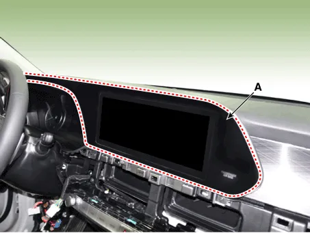
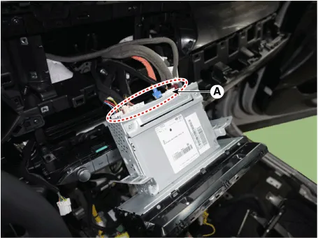
Using a flat-head screwdriver, remove the monitor cover (A).
|
| 4. |
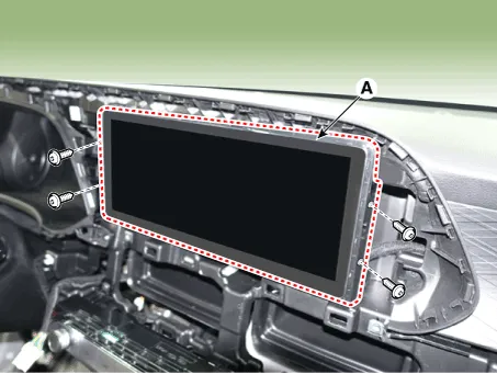
Remove the AVN head unit (A) after loosening mounting screws.
|
| 5. |
Remove the AVN head unit (A) after disconnecting the connectors and
cable.
|
| Installation |
| 1. |
Connect the audio unit connectors.
|
| 2. |
Install the AVN head unit.
|
| 3. |
Install the monitor cover.
|
| 4. |
Install the center fascia panel.
|
| 5. |
Connect the negative (-) battery terminal.
|

Description AVN system The AVN system has improved information search and easiness of manipulation for the driver by simplifying the system operation experience and unifying the display of the user information such as multimedia and car information.
Repair procedures Inspection 1. Troubleshooting for Speaker (1) Basic inspection of speaker Inspect the sound from speaker after verifying that the speaker mounting screws are removed and the wiring connector is connected to remove any possible vibration transmitted from body trims and surrounding parts.
Other information:
Hyundai Palisade (LX2) 2020-2026 Service Manual: Auto Defogging Sensor
Description and operation Description The auto defogging sensor is installed on the front window glass. The sensor judges and sends signal if moisture occurs to blow out wind for defogging. The air conditioner control module receives signal from the sensor and restrains moisture and eliminate defog by controlling the intak
Hyundai Palisade (LX2) 2020-2026 Service Manual: Warning Indicator
Components and components location Components 1. Warning indicator 2. SVM camera Repair procedures Removal 1. Disconnect the negative (-) battery terminal. 2.
Categories
- Manuals Home
- Hyundai Palisade Owners Manual
- Hyundai Palisade Service Manual
- Rear Heater Unit
- Automatic Transaxle System (A8LF1)
- Components and components location
- New on site
- Most important about car
