Hyundai Palisade (LX2): Audio / Audio Remote Control
Components and components location
| Components |

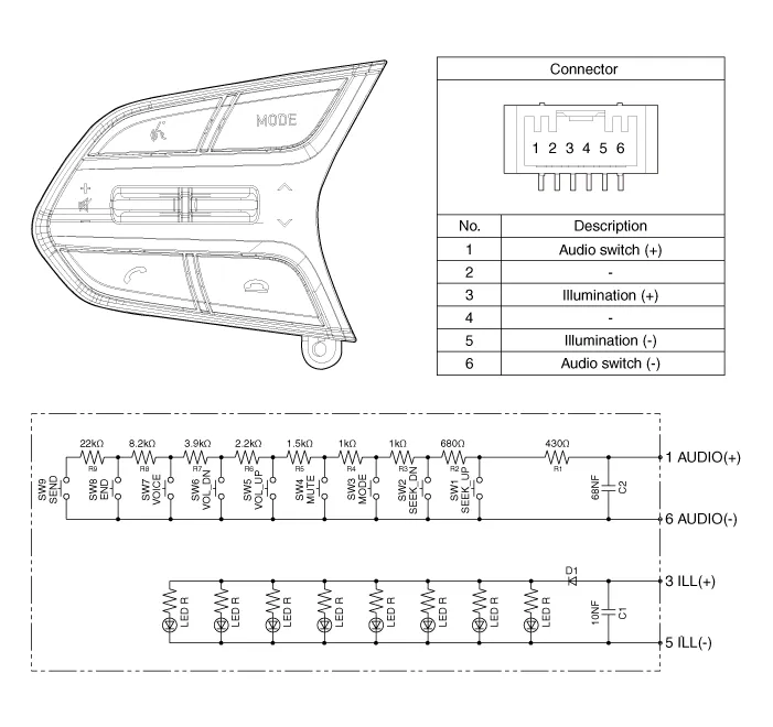
| 1. Remote control switch (LH
: Audio + Voice) |
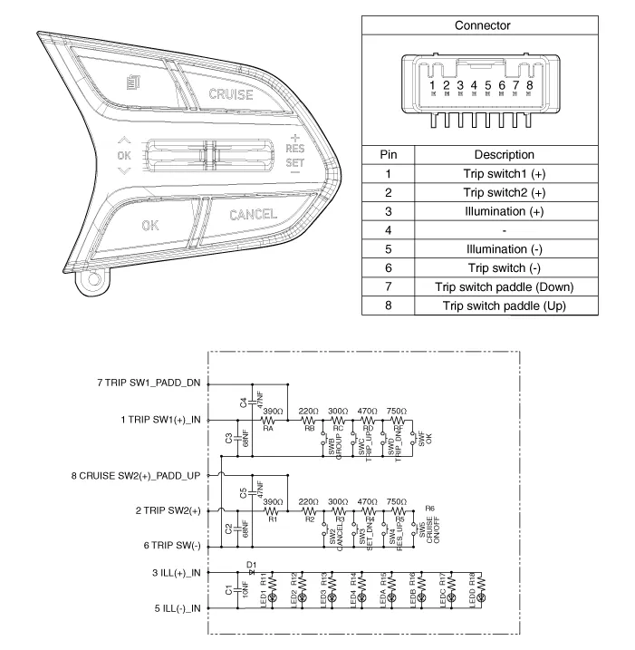
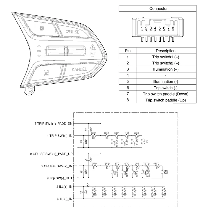
2. Remote control switch (RH
: Trip + Cruise) |
Schematic diagrams
| Circuit Diagram |
Repair procedures
| Inspection |
| 1. |
Check for resistance between terminals in left switch position.
[Audio / Bluetooth]
|

| 2. |
Check for resistance between terminals in right switch position.
[Trip / Cruise]
|
| Removal |
| 1. |
Disconnect the negative (-) battery terminal.
|
| 2. |
Remove the driver airbag module.
(Refer to Restraint - "Driver Airbag (DAB) Module and Clock Spring")
|
| 3. |
Remove the steering wheel.
(Refer to Steering System - "Steering Column and Shaft")
|
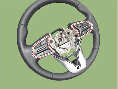
| 4. |
Remove the steering wheel cover (A) after loosening the screws.
|
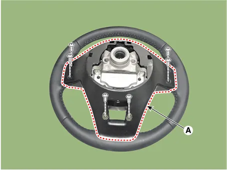
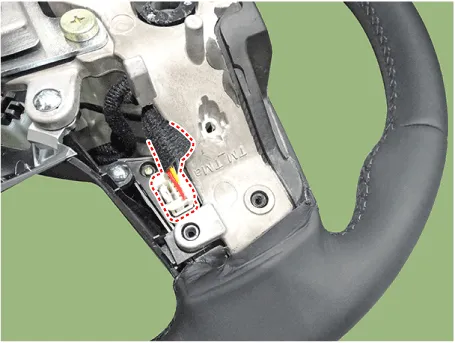
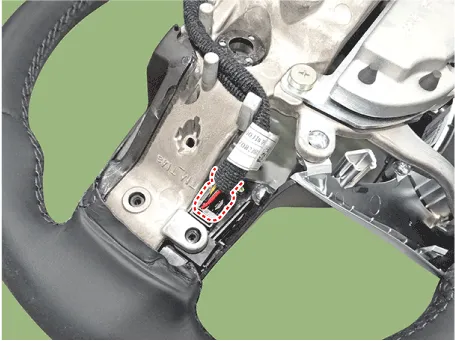
| 5. |
Loosen the screws and then disconnect the steering wheel remote control
switch connector.
|
| 6. |
Remove the remote control switchs (A).
|
| Installation |
| 1. |
Install the remote control switch on the steering wheel.
|
| 2. |
Install the steering wheel.
|
| 3. |
Reconnect the remote control switch connector and airbag connectors.
|

| 4. |
Install the driver airbag module.
|
| 5. |
Connect the negative (-) battery terminal.
|
Components and components location Components Repair procedures Removal 1. Remove the roof trim assembly.
Components and components location Components Repair procedures Removal 1. Disconnct the negative (-) battery terminal.
Other information:
Hyundai Palisade (LX2) 2020-2026 Service Manual: General safety information and caution
Instructions (R-134a) When Handling Refrigerant 1. R-134a liquid refrigerant is highly volatile. A drop on the skin of your hand could result in localized frostbite. When handling the refrigerant, be sure to wear gloves.
Hyundai Palisade (LX2) 2020-2026 Service Manual: Description and operation
Description • PDW consists of 8 sensors (front : 4 units, rear : 4 units) that are used to detect obstacles and transmit the result in three separate warning levels, the first, second and third to IBU via LIN communication.
Categories
- Manuals Home
- Hyundai Palisade Owners Manual
- Hyundai Palisade Service Manual
- Components and components location
- General Tightening Torque Table
- Electrochromatic Mirror (ECM) with homelink system
- New on site
- Most important about car
