Hyundai Palisade: Child restraint system (CRS) / Installing a Child Restraint System (CRS)
WARNING
Before installing your child restraint system always:
- Read and follow the instructions provided by the manufacturer of the child restraint.
- Read and follow the instructions regarding child restraint systems in this manual.
Failure to follow all warnings and instructions could increase the risk of the SERIOUS INJURY or DEATH if an accident occurs.
WARNING
If the vehicle head restraint prevents proper installation of a child seat (as described in the child seat system manual, the head restraint of the respective seating position shall be readjusted or entirely removed.
After selecting a proper child seat for your child, check to make sure it fits properly in your vehicle. Follow the instructions provided by the manufacturer when installing the child seat. Note these general steps when installing the seat to your vehicle:
- Properly secure the child restraint to the vehicle. All child restraints must be secured to the vehicle with the lap part of a lap/shoulder belt or with the LATCH system. If using the lap/shoulder belt for your child restraint, the convertible locking retractor should be pulled all the way out to engage the "automatic locking" mode. (See page 2-54.)
- Make sure the child restraint is firmly secured. After installing a child restraint to the vehicle, push and pull the seat forward-andback and side-to-side to verify that it is securely attached to the seat. A child restraint secured with a seat belt should be installed as firmly as possible. However, some side-to-side movement can be expected.
- Secure the child in the child restraint. Make sure the child is properly strapped in the child restraint according to the manufacturer instructions.
CAUTION
A child restraint in a closed vehicle can become very hot.To prevent burns, check the seating surface and buckles before placing your child in the child restraint.
- Lower Anchors and Tether for Children (LATCH System)
- Securing a child restraint with the LATCH anchors system
- Securing a child restraint seat with "Tether Anchor" system
- Securing a child restraint with lap/shoulder belt
 Selecting a Child Restraint
System (CRS)
Selecting a Child Restraint
System (CRS)
When selecting a CRS for your child,
always:
Make sure the CRS has a label
certifying that it meets applicable
Federal Motor Vehicle Safety
Standards (FMVSS 213)...
 Lower Anchors and Tether for
Children (LATCH System)
Lower Anchors and Tether for
Children (LATCH System)
The LATCH system holds a child
restraint during driving and in an accident.
This system is designed to
make installation of the child restraint
easier and reduce the possibility of
improperly installing your child
restraint...
Other information:
Hyundai Palisade (LX2) 2020-2025 Service Manual: Engine Control Module (ECM)
Schematic diagrams ECM Terminal and Input / Output Signal ECM Terminal Function Connector [A] Pin No Description Connected to 1 Ignition Coil (Cylinder #4) control output Ignition Coil (Cylinder #4) 2 Injector (Cylinder #3) [High] control output Injector (Cylinder #3) 3 Injector (Cylinder #5) [High] control output Injector (Cylinder #5) 4 Injector (Cylinder #1) [High] control output Injector (Cylinder #1) 5 Camshaft Position Sensor (CMPS) [Bank 2 / Exhaust] signal input Camshaft Position Sensor (CMPS) [Bank 2 / Exhaust] 6 Camshaft Position Sensor (CMPS) [Bank 2 / Intake] signal input Camshaft Position Sensor (CMPS) [Bank 2 / Intake] 7 Throttle Position Sensor (TPS) 2 signal input Throttle Position Sensor (TPS) 2 8 - 9 Rail Pressure Sensor (RPS) signal input Rail Pressure Sensor (RPS) 10 CVVT Oil Temperature Sensor (OTS) signal input CVVT Oil Temperature Sensor (OTS) 11 - 12 - 13 Sensor power (+5V) CVVT Oil Temperature Sensor (OTS) Manifold Absolute Pressure Sensor (MAPS) 14 - 15 - 16 - 17 - 18 - 19 ETC Motor [-] control output ETC Motor 20 Heated Oxygen Sensor (HO2S) [Bank 1 / Sensor 1] Heater control output Heated Oxygen Sensor (HO2S) [Bank 1 / Sensor 1] 21 Heated Oxygen Sensor (HO2S) [Bank 2 / Sensor 1] Heater control output Heated Oxygen Sensor (HO2S) [Bank 2 / Sensor 1] 22 Ignition Coil (Cylinder #5) control output Ignition Coil (Cylinder #5 23 Injector (Cylinder #6) [High] control output Injector (Cylinder #6) 24 Injector (Cylinder #2) [High] control output Injector (Cylinder #2) 25 Injector (Cylinder #4) [High] control output Injector (Cylinder #4) 26 Camshaft Position Sensor (CMPS) [Bank 1 / Exhaust] signal input Camshaft Position Sensor (CMPS) [Bank 1 / Exhaust] 27 Camshaft Position Sensor (CMPS) [Bank 1 / Intake] signal input Camshaft Position Sensor (CMPS) [Bank 1 / Intake] 28 Intake Air Temperature Sensor (IATS) signal input Intake Air Temperature Sensor (IATS) 29 Manifold Absolute Pressure Sensor (MAPS) signal input Manifold Absolute Pressure Sensor (MAPS) 30 - 31 - 32 - 33 - 34 Sensor power (+5V) Camshaft Position Sensor (CMPS) [Bank 1 / Exhaust] Camshaft Position Sensor (CMPS) [Bank 2 / Intake] 35 - 36 Sensor power (+5V) Camshaft Position Sensor (CMPS) [Bank 1 / Intake] Camshaft Position Sensor (CMPS) [Bank 2 / Exhaust] 37 - 38 Purge Control Solenoid Valve (PCSV) control output Purge Control Solenoid Valve (PCSV) 39 - 40 ETC Motor [+] control output ETC Motor 41 - 42 - 43 Ignition Coil (Cylinder #1) control output Ignition Coil (Cylinder #1) 44 Injector (Cylinder #6) [Low] control output Injector (Cylinder #6) 45 Injector (Cylinder #3) [Low] control output Injector (Cylinder #3) 46 Injector (Cylinder #2) [Low] control output Injector (Cylinder #2) 47 Sensor ground Camshaft Position Sensor (CMPS) [Bank 1 / Exhaust] Camshaft Position Sensor (CMPS) [Bank 2 / Intake] 48 Sensor ground Manifold Absolute Pressure Sensor (MAPS) Oil Pressure Sensor (OPS) 49 Sensor ground Camshaft Position Sensor (CMPS) [Bank 1 / Intake] Camshaft Position Sensor (CMPS) [Bank 2 / Exhaust] 50 - 51 - 52 - 53 - 54 Engine Coolant Temperature Sensor (ECTS) signal input Engine Coolant Temperature Sensor (ECTS) 55 Sensor Shield Crankshaft Position Sensor (CKPS) Knock Sensor (KS) #1 [Bank 1] Knock Sensor (KS) #2 [Bank 2] 56 Sensor power (+5V) Rail Pressure Sensor (RPS) 57 - 58 Sensor ground Engine Coolant Temperature Sensor (ECTS) Rail Pressure Sensor (RPS) 59 Sensor ground Throttle Position Sensor (TPS) 1 Throttle Position Sensor (TPS) 2 60 Variable Intake Solenoid (VIS) Valve 1 control output Variable Intake Solenoid (VIS) Valve 1 61 Variable Intake Solenoid (VIS) Valve 2 control output Variable Intake Solenoid (VIS) Valve 2 62 - 63 - 64 Ignition Coil (Cylinder #2) control output Ignition Coil (Cylinder #2) 65 Injector (Cylinder #1) [Low] control output Injector (Cylinder #1) 66 Injector (Cylinder #4) [Low] control output Injector (Cylinder #4) 67 Injector (Cylinder #5) [Low] control output Injector (Cylinder #5) 68 Crankshaft Position Sensor (CKPS) [High] signal input Crankshaft Position Sensor (CKPS) 69 Crankshaft Position Sensor (CKPS) [Low] signal input Crankshaft Position Sensor (CKPS) 70 - 71 - 72 Oil pressure switch signal input Oil Pressure Sensor (OPS) 73 - 74 - 75 Throttle Position Sensor (TPS) 1 signal input Throttle Position Sensor (TPS) 1 76 Knock Sensor (KS) [Bank 1] [Low] signal input Knock Sensor (KS) [Bank 1] 77 Knock Sensor (KS) [Bank 2] [Low] signal input Knock Sensor (KS) [Bank 2] 78 Sensor ground Heated Oxygen Sensor (HO2S) [Bank 2 / Sensor 2] 79 Rc/Rp (Pump Cell Voltage) Heated Oxygen Sensor (HO2S) [Bank 2 / Sensor 1] 80 VS+ (NERNST Cell Voltage) Heated Oxygen Sensor (HO2S) [Bank 2 / Sensor 1] 81 Heated Oxygen Sensor (HO2S) [Bank 2 / Sensor 2] signal input Heated Oxygen Sensor (HO2S) [Bank 2 / Sensor 2] 82 VS+ (NERNST Cell Voltage) Heated Oxygen Sensor (HO2S) [Bank 1 / Sensor 1] 83 Rc (Compensative Resistance) Heated Oxygen Sensor (HO2S) [Bank 1 / Sensor 1] 84 Oil Pressure Solenoid Valve control output Oil Pressure Solenoid Valve 85 Ignition Coil (Cylinder #6) control output Ignition Coil (Cylinder #6) 86 Ignition Coil (Cylinder #3) control output Ignition Coil (Cylinder #3) 87 Fuel Pressure Control Valve (FPCV) [High] control output Fuel Pressure Control Valve (FPCV) 88 Fuel Pressure Control Valve (FPCV) [Low] control output Fuel Pressure Control Valve (FPCV) 89 Heated Oxygen Sensor (HO2S) [Bank 2 / Sensor 2] Heater control output Heated Oxygen Sensor (HO2S) [Bank 2 / Sensor 2] 90 Heated Oxygen Sensor (HO2S) [Bank 1 / Sensor 2] Heater control output Heated Oxygen Sensor (HO2S) [Bank 1 / Sensor 2] 91 CVVT Oil Control Valve (OCV) [Bank 2 / Exhaust] control output CVVT Oil Control Valve (OCV) [Bank 2 / Exhaust] 92 CVVT Oil Control Valve (OCV) [Bank 1 / Exhaust] control output CVVT Oil Control Valve (OCV) [Bank 1 / Exhaust] 93 Variable Force Solenoid (VFS) [Bank 2 / Intake] control output Variable Force Solenoid (VFS) [Bank 2 / Intake] 94 Variable Force Solenoid (VFS) [Bank 1 / Intake] control output Variable Force Solenoid (VFS) [Bank 1 / Intake] 95 - 96 Sensor power (+5V) Throttle Position Sensor (TPS) 1 Throttle Position Sensor (TPS) 2 97 Knock Sensor (KS) [Bank 1] [High] signal input Knock Sensor (KS) [Bank 1] 98 Knock Sensor (KS) [Bank 2] [High] signal input Knock Sensor (KS) [Bank 2] 99 Sensor ground Heated Oxygen Sensor (HO2S) [Bank 1 / Sensor 2] 100 - 101 Rc (Compensative Resistance) Heated Oxygen Sensor (HO2S) [Bank 2 / Sensor 1] 102 VS-/IP- (Common ground) Heated Oxygen Sensor (HO2S) [Bank 2 / Sensor 1] 103 Heated Oxygen Sensor (HO2S) [Bank 1 / Sensor 2] signal input Heated Oxygen Sensor (HO2S) [Bank 1 / Sensor 2] 104 VS-/IP- (Common ground) Heated Oxygen Sensor (HO2S) [Bank 1 / Sensor 1] 105 Rc/Rp (Pump Cell Voltage) Heated Oxygen Sensor (HO2S) [Bank 1 / Sensor 1] Connector [K] Pin No Description Connected to 1 ECM ground Chassis ground 2 ECM ground Chassis ground 3 Battery power (B+) Main Relay 4 ECM ground Chassis ground 5 Battery power (B+) Main Relay 6 Battery power (B+) Main Relay 7 - 8 - 9 - 10 - 11 - 12 - 13 Sensor ground A/C Pressure Transducer (APT) 14 Immobilizer communication line Immobilizer Control Module 15 Fuel Level Sender (FLS) signal input [Fuel pump] Fuel Level Sender (FLS) 16 - 17 - 18 - 19 - 20 Sensor power (+5V) Accelerator Position Sensor (APS) 1 21 Main Relay control output Main Relay 22 - 23 - 24 - 25 - 26 - 27 - 28 Accelerator Position Sensor (APS) 2 signal input Accelerator Position Sensor (APS) 2 29 - 30 - 31 - 32 Fuel Level Sender (FLS) signal input [Sub Fuel Sender] Sub Fuel Level Sender 33 Fuel Pump Relay control output Fuel Pump Relay 34 - 35 Sensor power (+5V) A/C Pressure Transducer (APT) 36 Sensor power (+5V) Accelerator Position Sensor (APS) 2 37 - 38 Vehicle speed signal input VDC control module 39 - 40 - 41 Start signal input Start Relay 42 - 43 - 44 - 45 - 46 - 47 Sensor ground Accelerator Position Sensor (APS) 2 48 - 49 Brake Switch [Test] signal input Brake Switch 50 - 51 - 52 Sensor ground Accelerator Position Sensor (APS) 1 53 - 54 - 55 - 56 - 57 - 58 - 59 - 60 P-CAN [Low] Other control module, Data Link Connector (DLC), Multi-Purpose Check Connector 61 - 62 - 63 - 64 A/C Pressure Transducer (APT) signal input A/C Pressure Transducer (APT) 65 - 66 - 67 - 68 - 69 LIN (Local Interconnect Network) Serial Bus Line Battery Sensor 70 - 71 Cooling Fan Relay control output Cooling Fan Relay 72 Engine speed signal output Integrated Body Control Unit (IBU) 73 - 74 - 75 - 76 - 77 P-CAN [High] Other control module, Data Link Connector (DLC), Multi-Purpose Check Connector 78 - 79 Start Relay control output Start Relay 80 - 81 - 82 Accelerator Position Sensor (APS) 1 signal input Accelerator Position Sensor (APS) 1 83 Brake Switch [Light] signal input Brake Switch 84 - 85 - 86 - 87 - 88 - 89 - 90 - 91 - ECM Terminal Input/ Output signal Connector [A] Pin No Description Condition Type Level 1 Ignition Coil (Cylinder #4) control output Idle Pulse Vpeak = 400V Frequency : 0 - 58...
Hyundai Palisade (LX2) 2020-2025 Owner's Manual: Warning Message
Hands-off warning Keep hands on steering wheel If the driver takes their hands off the steering wheel for several seconds while the HDA system is activated, the system will warn the driver. Information If the steering wheel is held with a light grip, the message may appear because the HDA system may not recognize that the driver has their hands on the steering wheel...
Categories
- Manuals Home
- 1st Generation Palisade Owners Manual
- 1st Generation Palisade Service Manual
- How to reset the power liftgate
- Electronic Child Safety Lock System
- Normal Maintenance Schedule (3.8 GDI)
- New on site
- Most important about car
Air Bag - Advanced Supplemental Restraint System
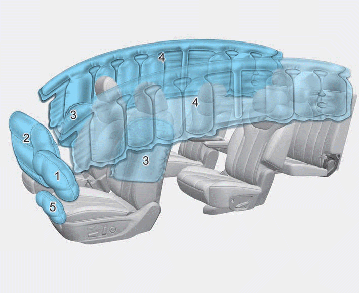
1. Driver's front air bag
2. Passenger's front air bag
3. Side air bag
4. Curtain air bag
5. Driver’s knee airbag
This vehicle is equipped with an Advanced Supplemental Air Bag System for the driver's seat and front passenger's seats.
