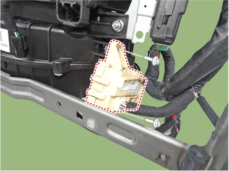
Hyundai Palisade (LX2): Fuses And Relays / ICM (Integrated Circuit Module) Relay Box
Description and operation
| Description |
Repair procedures
| Inspection |
| 1. |
There should be continuity between the No.15 and No.7 terminals when
power and ground are connected to the No.15 and No.14 in the ICM-A.
|
| 2. |
There should be continuity between the No.10 and No.12 terminals when
power and ground are connected to the No.15 and No.14 in the ICM-A.
|
| 1. |
There should be continuity between the No.11 and No.12 terminals when
power and ground are connected to the No.11 and No.1 in the ICM-A.
|
| 2. |
There should be continuity between the No.10 and No.7 terminals when
power and ground are connected to the No.11 and No.1 in the ICM-A.
|
Description and operation Dscription and Operation ICU (Integrated Central Control Unit) ICU (Integrated Central Control Unit) is an integrated model of smart junction block and central gateway.
Other information:
Hyundai Palisade (LX2) 2020-2026 Service Manual: Rear Blower Motor
Repair procedures Replacement 1. Disconnect the negative (-) battery terminal. 2. Remove the luggage side trim (Refer to Body - "Luggage Side Trim ") 3. Separate the rear blower motor connector (A), loosen the mounting screws and remov
Hyundai Palisade (LX2) 2020-2026 Service Manual: Repair procedures
Inspection 1. Turn the ignition switch ON. 2. Manually operate the control switch and measure the voltage of the blower motor. 3. Select the control switch to raise the voltage until it reaches high speed.
Categories
- Manuals Home
- Hyundai Palisade Owners Manual
- Hyundai Palisade Service Manual
- Body (Interior and Exterior)
- Electrochromatic Mirror (ECM) with homelink system
- Scheduled maintenance services
- New on site
- Most important about car
