Hyundai Palisade (LX2): Towing / General information
If the vehicle needs to be towed, call a professional towing service. Never
tow vehicle with just a rope or chain. It is very dangerous.
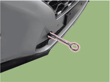
[Front]
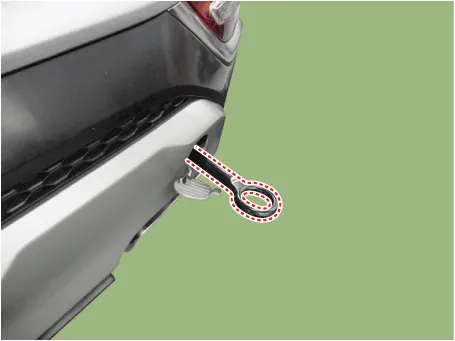
[Rear]
Emergency Towing
There are three popular methods of towing a vehicle :
| – |
The operator loads the vehicle on the back of truck. This is best way
of transporting the vehicle.
|
| – |
The tow truck uses two pivoting arms that go under the tires of the
driving axle and lift them off the ground. The other two wheels remain
on the ground.
|
| – |
The tow truck uses metal cables with hooks on the ends. These hooks
go around parts of the frame or suspension, and the cables lift that
end of the vehicle off the ground. The vehicle's suspension and body
can be seriously damaged if this method of towing is attempted.
|
If the vehicle cannot be transported by flat-bed, should be towed with the wheels
of the driving axle off the ground and do the following :
Manual Transaxle
| • |
Release the parking brake.
|
| • |
Shift the Transaxle to neutral
|
Automatic Transaxle
| • |
Release the parking brake.
|
| • |
Shift to [D] position, then [N] position.
|
| • |
The vehicle equipped with full-time 4WD should be only transported
on a flat-bed.
|
| • |
The CVT vehicles should be only transported on a flat-bed or
towed by wheel lift towing which the wheels of the driving axle
are lifted off the ground.
|
| • |
Improper towing preparation will damage the transaxle. Follow
the procedure above exactly. If you cannot shift the transaxle
or start the engine(automatic transaxle), your vehicle must
be transported on a flatbed.
|
| • |
It is the best to tow vehicle no farther than 30km (19miles),
and keep the speed below 50km/h (30mph).
(For the CVT and full-time 4WD (CVT/AT) vehicles, limit the
towing distance and speed to 1.5km (1 mile) and 15km/h (10 mph).)
|
| • |
Trying to lift or tow your vehicle by the bumpers will cause
serious damage to the vehicle. The bumpers are not designed
to support the vehicle's weight.
|
|
General information
Basic Service Symbols
There are five primary symbols used to complement illustrations. These symbols
indicate the part to apply such materials during service.
Other information:
Description and operation
Description
The photo sensor is located at the center of the defrost nozzles.
The photo sensor contains a photovoltaic (sensitive to sunlight) diode. The
solar radiation received by its light receiving portion, generates an electromotive
force in proportion to the amount of radiation received wh
Description and Operation
Blcok Diagram
•
This system monitors the driving situations through the radar
and the camera. Thus, for a situation out of the sensing range,
the system may not normally operate.

