Hyundai Palisade (LX2): Brake System / Front Disc Brake
Components and components location
| Components |
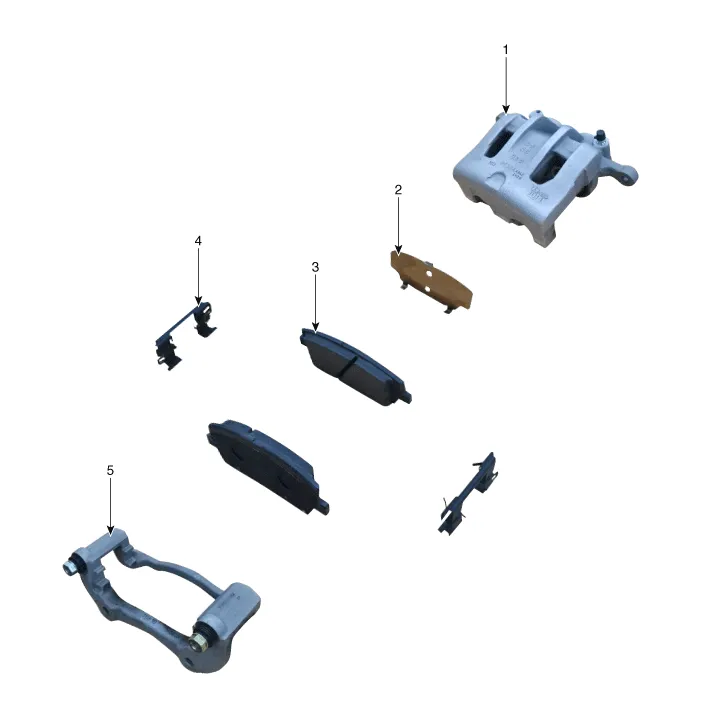
| 1. Caliper body 2. Pad inner shim 3. Brake pad |
4. Pad retainer 5. Caliper carrier |
Repair procedures
| Removal |
|

| 1. |
Loosen the wheel nuts slightly.
Raise the vehicle, and make sure it is securely supported.
|
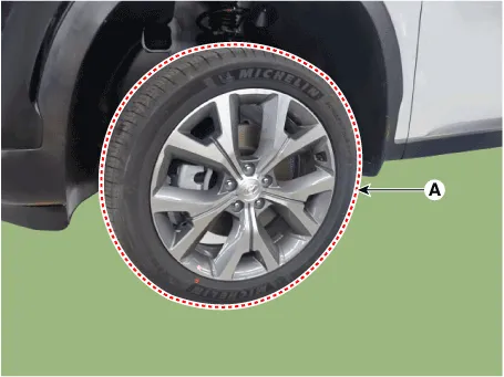
| 2. |
Remove the front wheel and tire (A) from front hub.
|

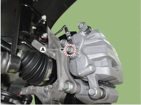
| 3. |
Remove the hose after loosening the brake hose bolt (A) from the caliper.
|
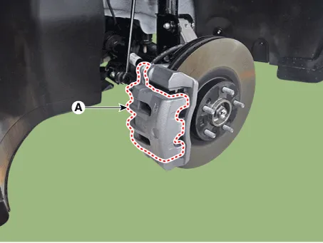
| 4. |
Remove the caliper body (A) by loosening the guided rod bolt.
|
| 5. |
Remove the brake pad (A).
|
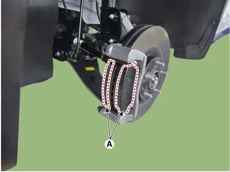
| 6. |
Remove the pad retainer (A).
|
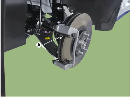
| 7. |
Remove the caliper carrier (A) by loosening the caliper mouniting bolts.
|

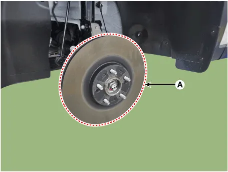
| 8. |
Remove the front brake disc (A) by loosening the screws.
|
| Inspection |
Front Brake Disc Thickness Check
| 1. |
Check the brake disc for damage and cracks.
|
| 2. |
Remove all rust and contamination from the surface, and measure the
disc thickness at 24 points, at least, of same distance (5mm) from the
brake disc outer circle.
|

| 3. |
If wear exceeds the limit, replace the discs and pad assembly left and
right of the vehicle.
|
Front Brake Disc Runout Check
| 1. |
Place a dial gauge about 10mm (0.20 in) from the outer circumference
of the brake disc, and measure the runout of the disc.
|

| 2. |
If the runout of the brake disc exceeds the limit specification, replace
the disc, and then measure the runout again.
|
| 3. |
If the runout does not exceed the limit specification, install the brake
disc after turning it 180° and then check the runout of the brake disc
again.
|
| Installation |
| 1. |
To install, reverse the removal procedures.
|
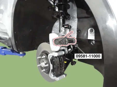
| 2. |
Use a SST (09581-11000) when installing the brake caliper assembly.
|
| 3. |
After installation, bleed the brake system.
(Refer to Brake System - "Brake System Bleeding")
(Refer to Brake System - "ESP System Bleeding)
|
Components and components location Components 1. Brake member assembly 2. Stop lamp switch 3. Brake pedal arm assembly 4.
Components and components location Components 1. EPB actuator 2. Caliper body 3. Guide rod pin 4. Guide rod boot 5.
Other information:
Hyundai Palisade (LX2) 2020-2026 Service Manual: Repair procedures
Replacement 1. Disconnect the negative (-) battery terminal. 2. Remove the luggage side trim (Refer to Body - "Luggage Side Trim ") 3. Separate the rear mode actuator connector (A), loosen the mounting screws and remove the rear mode ac
Hyundai Palisade (LX2) 2020-2026 Service Manual: Components and components location
Categories
- Manuals Home
- Hyundai Palisade Owners Manual
- Hyundai Palisade Service Manual
- Rear Heater Unit
- Electronic Child Safety Lock System
- Scheduled maintenance services
- New on site
- Most important about car

Copyright © 2026 www.hpalisadelx.com - 0.0105