Hyundai Palisade (LX2): Brake System / Rear Disc Brake
Components and components location
| Components |

| 1. EPB actuator 2. Caliper body 3. Guide rod pin 4. Guide rod boot 5. Caliper carrier |
6. Pad inner shim 7. Brake pad 8. Pad retainer 9. Pad return spring |
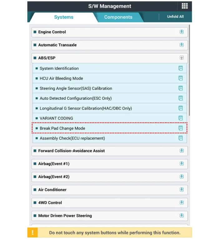
Repair procedures
| Removal |
|

| 1. |
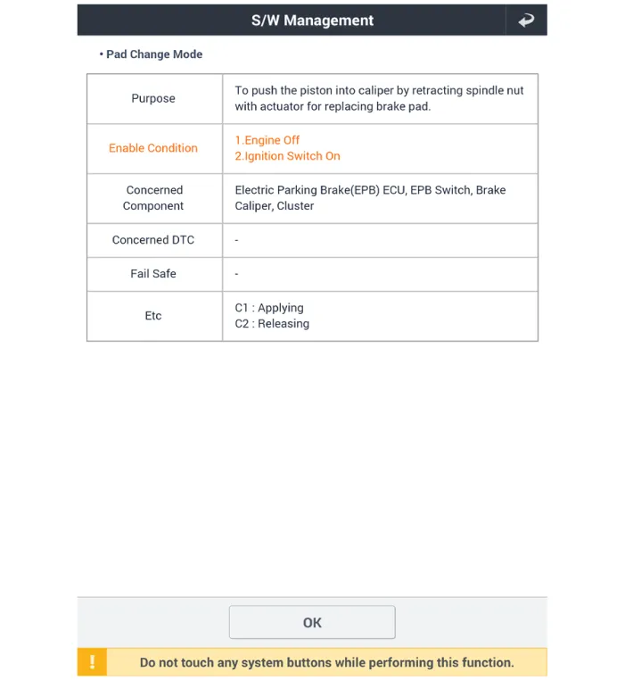
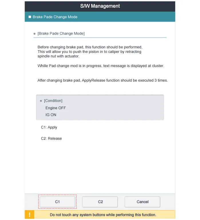
Before removing the rear caliper, perform “Brake Pad Replacement Mode”
using the GDS.
|
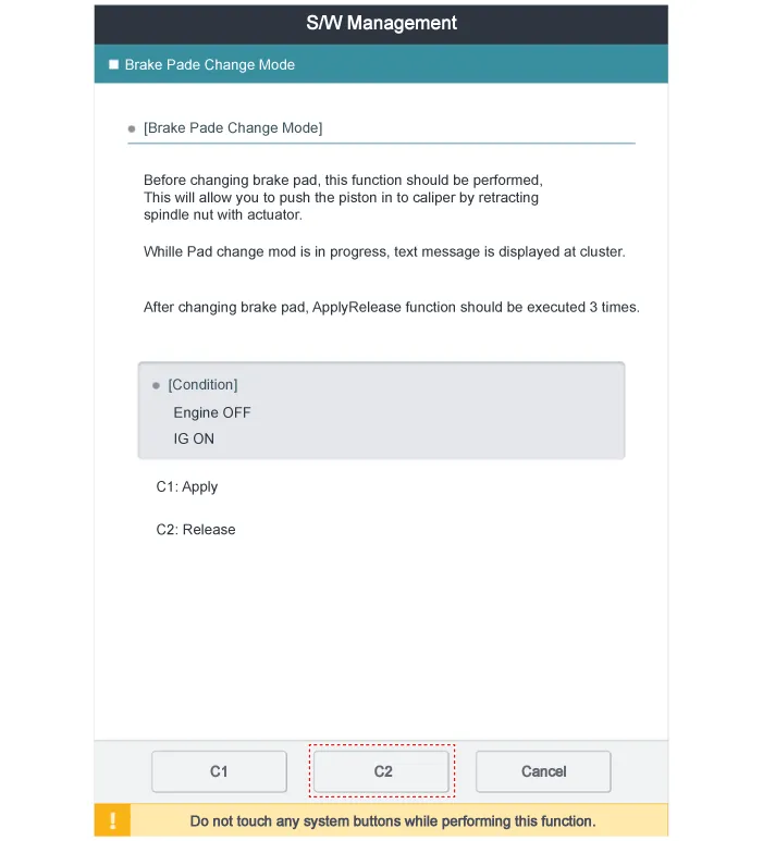
| 2. |
Select C2 (Release) on the screen below.
|
| 3. |
Loosen the wheel nuts slightly.
Raise the vehicle, and make sure it is securely supported.
|
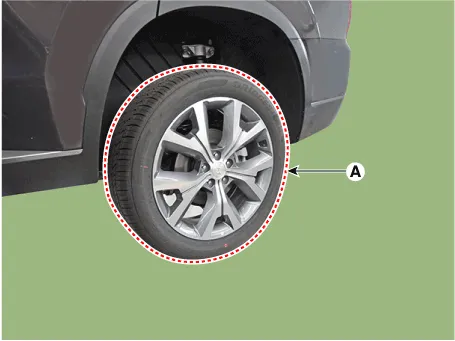
| 4. |
Remove the rear wheel and tire (A) from the rear hub.
|

| 5. |
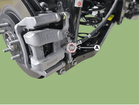
Disconnect the EPB actuator connector (A).
|
| 6. |
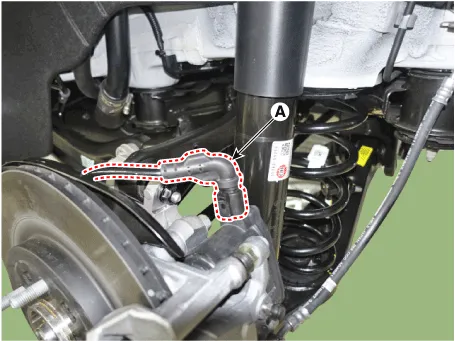
Remove the hose after loosening the brake hose bolt (A) from the caliper.
|
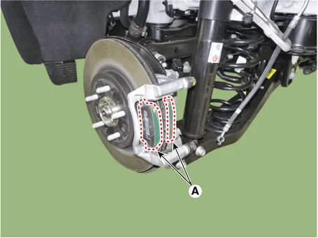
| 7. |
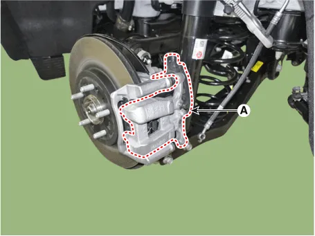
Remove the caliper body (A) after loosening the guide rod bolt.
|
| 8. |
Remove the return spring (A).
|
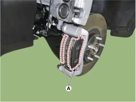
| 9. |
Remove the brake pad (A).
|
| 10. |
Remove the pad retainer (A).
|
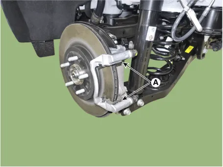
| 11. |
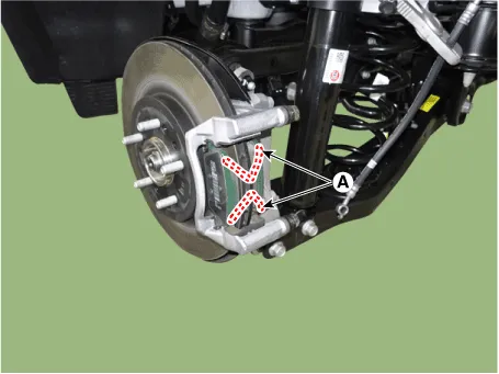
Remove the caliper carrier (A) after loosening the caliper mounting
bolt.
|

| 12. |
Remove the rear brake disc (A) after loosening the screw.
|
| Inspection |
| 1. |
Check the brake disc for damage and cracks.
|
| 2. |
Remove all rust and contamination from the surface, and measure the
disc thickness at 24 points, at least, of same distance (5mm) from the
brake disc outer circle.
|

| 3. |
If wear exceeds the limit, replace the discs and pad assembly left and
right of the vehicle.
|
| 1. |
Place a dial gauge about 10mm (0.20 in.) from the outer circumference
of the brake disc, and measure the runout of the disc.
|

| 2. |
If the runout of the brake disc exceeds the limit specification, replace
the disc, and then measure the runout again.
|
| 3. |
If the runout cannot be corrected by changing the position of the brake
disc, replace the brake disc.
|
| Installation |
| 1. |
To install, reverse the removal procedures.
|
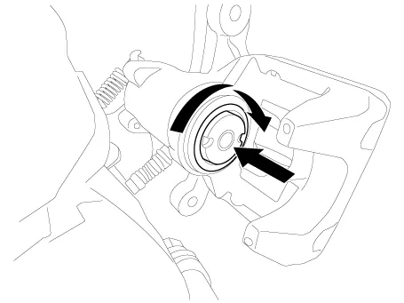
| 2. |
When istalling, press and rotate the piston into the caliper body until
it is fully retracted.
|

| 3. |
After installation, bleed the brake system.
(Refer to Brake system - "Brake system Bleeding")
(Refer to Brake System - "ESP System Bleeding)
|
| 4. |
After installing the rear caliper (EPB applied), perform “Brake Pad
Replacement Mode” using the GDS.
|


| 5. |
Select C1 (Apply) on the screen below.
|
| 6. |
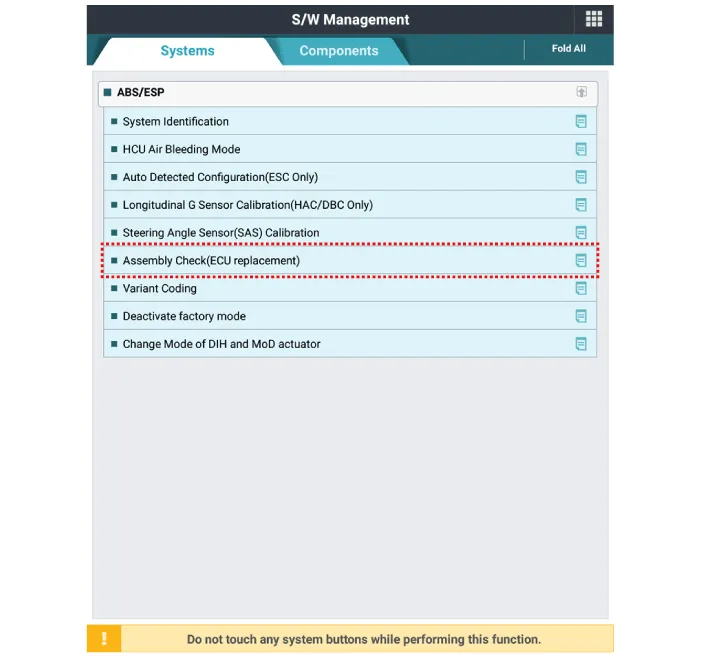
After replacing the rear caliper, make sure that the caliper is installed
correctly by performing “Check assembling (ECU replaced)” from the option.
|
Components and components location Components 1. Caliper body 2. Pad inner shim 3. Brake pad 4. Pad retainer 5.
Repair procedures Replacement • Be careful not to damage the parts located under the vehicle (floor under cover, fuel filter, fuel tank and canister) when raising the vehicle using the lift.
Other information:
Hyundai Palisade (LX2) 2020-2026 Service Manual: Auto Defogging Actuator
Description and operation Description The auto defogging sensor is installed on the front window glass. The sensor judges and sends signal if moisture occurs to blow out wind for defogging. The air conditioner control module receives a signal from the sensor and restrains moisture and eliminates defog by the intake actuato
Hyundai Palisade (LX2) 2020-2026 Service Manual: Description and operation
Description The smart cruise control system allows a driver to program the vehicle to control the speed and following distance by detecting the vehicle ahead without depressing the brake pedal or the accelerator pedal. 1.
Categories
- Manuals Home
- Hyundai Palisade Owners Manual
- Hyundai Palisade Service Manual
- How to reset the power liftgate
- Automatic Transaxle Fluid (ATF)
- Electrochromatic Mirror (ECM) with homelink system
- New on site
- Most important about car
