Hyundai Palisade (LX2): Automatic Transaxle Control System / Electric Shift Button
Repair procedures
| Removal |
| 1. |
Turn ignition switch OFF and disconnect the negative (-) battery cable.
|
| 2. |
Remove the console upper cover.
(Refer to Body - "Floor Console Assembly")
|
| 3. |
Remove the electric shift button (A).
|
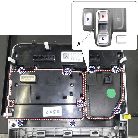
| 4. |
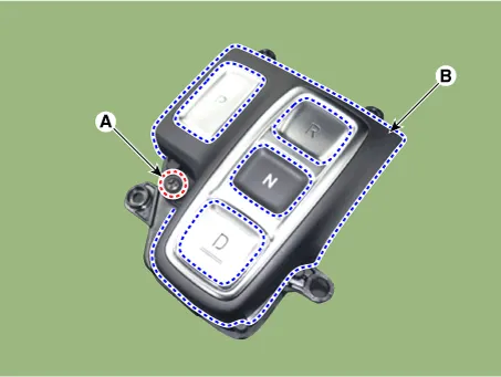
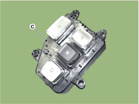
Loosen the screw (A) and then disconnect the upper cover (B) with the
shift button module (C)
|
| Installation |
| 1. |
To install, reverse the removal procedure.
|
Specifications Specification Item Specification Power supply (V) 4.5 - 5.5V Output type Shifting range Non-contact (2 channel PWM signal) Description and operation Description Output position signal(P,R,N,D) by the actuator operation to the controller (SBW Control Unit_SCU).
Components and components location Component Location 1. SBW Control Unit (SCU) Repair procedures Removal 1.
Other information:
Hyundai Palisade (LX2) 2020-2026 Service Manual: Wireless Charging Lamp
Components and positions Components Repair procedures Removal Handling wireless charging system parts by wet hands may cause electric shock.
Hyundai Palisade (LX2) 2020-2026 Service Manual: A/C Pressure Transducer
Description and operation Description The A/C Pressure Transducer (APT) converts the pressure value of high pressure line into voltage value after measuring it. By converted voltage value, engine ECU controls the cooling fan by operating it high speed or low speed.
Categories
- Manuals Home
- Hyundai Palisade Owners Manual
- Hyundai Palisade Service Manual
- Lift and Support Points
- PTG Spindle
- Brake bleeding procedures
- New on site
- Most important about car
