Hyundai Palisade (LX2): Engine Control System / Description and operation
If the Gasoline Engine Control system components (sensors, ECM, injector, etc.)
fail, interruption to the fuel supply or failure to supply the proper amount
of fuel for various engine operating conditions will result. The following situations
may be encountered.
| 1. |
Engine is hard to start or does not start at all.
|
If any of the above conditions are noted, first perform a routine diagnosis
including the basic engine checks (ignition system malfunction, incorrect engine
adjustment, etc.). Then, inspect the Gasoline Engine Control system components
with the HI-SCAN (Pro).
| • |
Before removing or installing any part, read the diagnostic
trouble codes and then disconnect the negative (-) battery terminal.
|
| • |
Before disconnecting the cable from battery terminal, turn the
ignition switch to OFF. Removal or connection of the battery
cable during engine operation or while the ignition switch is
ON could cause damage to the ECM.
|
| • |
The control harnesses between the ECM and heated oxygen sensor
are covered by the shielded ground wires to the body in order
to prevent the influence of ignition noises and radio interference.
If the shielded wire is faulty, the control harness must be
replaced.
|
| • |
When checking the generator for the charging state, do not disconnect
the positive (+) battery terminal to protect the ECM from damage
due to the voltage.
|
| • |
When charging the battery with the external charger, disconnect
the vehicle side battery terminals to prevent damage to the
ECM.
|
|
Malfunction Indicator Lamp (MIL)
[EOBD]
A malfunction indicator lamp illuminates to notify the driver that there is
a problem with the vehicle. However, the MIL will go out automatically after
3 sequential driving cycles without the same malfunction. Immediately after
the ignition switch is turned on (ON position without starting), the MIL will
illuminate continuously to indicate that the MIL operates normally.
Faults with the following items will illuminate the MIL.
| • |
Manifold Absolute Pressure Sensor (MAPS)
|
| • |
Intake Air Temperature Sensor (IATS)
|
| • |
Engine Coolant Temperature Sensor (ECTS)
|
| • |
Throttle Position Sensor (TPS) [integrated into ETC Module]
|
| • |
Upstream Oxygen Sensor
|
| • |
Upstream Oxygen Sensor Heater
|
| • |
Downstream Oxygen Sensor
|
| • |
Downstream Oxygen Sensor Heater
|
| • |
Crankshaft Position Sensor (CKPS)
|
| • |
Camshaft Position Sensor (CMPS)
|
| • |
Evaporative Emission Control System
|
| • |
Vehicle Speed Sensor (VSS)
|
| • |
ETC Motor [integrated into ETC Module]
|
| • |
MIL-on Request Signal
|
| • |
Refer to "Inspection CHART FOR DIAGNOSTIC TROUBLE CODES (DTC)"
for more information.
|
|
[NON-EOBD]
A malfunction indicator lamp illuminates to notify the driver that there is
a problem with the vehicle. However, the MIL will go out automatically after
3 sequential driving cycles without the same malfunction. Immediately after
the ignition switch is turned on (ON position without starting), the MIL will
illuminate continuously to indicate that the MIL operates normally.
Faults with the following items will illuminate the MIL
| • |
Heated oxygen sensor (HO2S)
|
| • |
Manifold Absolute Pressure Sensor (MAPS)
|
| • |
Throttle Position Sensor (TPS) [integrated into ETC Module]
|
| • |
Engine coolant temperature sensor (ECTS)
|
| • |
ETC Motor [integrated into ETC Module]
|
| • |
Refer to "Inspection CHART FOR DIAGNOSTIC TROUBLE CODES (DTC)"
for more information.
|
|
[Inspection]
| 1. |
After turning ON the ignition key, ensure that the light illuminates
for about 5 seconds and then goes out.
|
| 2. |
If the light does not illuminate, check for an open circuit in the harness,
a blown fuse or a blown bulb.
|
Self-Diagnosis
The ECM monitors the input/output signals (some signals at all times and the
others under specified conditions). When the ECM detects an irregularity, it
records the diagnostic trouble code, and outputs the signal to the Data Link
connector. The diagnosis results can be read with the MIL or HI-SCAN (Pro).
Diagnostic Trouble Codes (DTC) will remain in the ECM as long as battery power
is maintained. The diagnostic trouble codes will, however, be erased when the
battery terminal or ECM connector is disconnected, or by the HI-SCAN (Pro).
| • |
If a sensor connector is disconnected with the ignition switch
turned on, the diagnostic trouble code (DTC) is recorded. In
this case, leave the negative (-) battery terminal disconnected
for 15 seconds or more until the diagnostic memory is erased.
|
|
Relationship between DTC and Driving Pattern in EOBD System
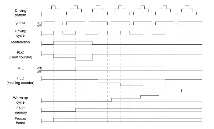
| 1. |
When the same malfunction is detected and maintained during two sequential
driving cycles, the MIL will automatically illuminate.
|
| 2. |
The MIL will go out automatically if no fault is detected after 3 sequential
driving cycles.
|
| 3. |
A Diagnostic Trouble Code (DTC) is recorded in ECM memory when a malfunction
is detected after two sequential driving cycles. The MIL will illuminate
when the malfunction is detected on the second driving cycle.
If a misfire is detected, a DTC will be recorded, and the MIL will illuminate,
immediately after a fault is first detected.
|
| 4. |
A Diagnostic Trouble Code (DTC) will be automatically erased from ECM
memory if the same malfunction is not detected for 40 driving cycles.
| •
|
A "warm-up cycle" means sufficient vehicle operation
such that the coolant temperature rises by at least
4°C (40°F) from engine starting and reaches a minimum
temperature of 71°C (160°F).
|
| •
|
A "driving cycle" consists of engine startup, and vehicle
operation beyond the beginning of closed loop operation.
|
|
|
Components Location
1. ECM
(Engine Control Module)
2. Intake Air Temperature Sensor (IATS)
3. Manifold Absolute Pressure Sensor (MAPS)
4.
Schematic diagrams
ECM Terminal and Input /
Output Signal
ECM Terminal Function
Connector [A]
Pin No
Description
Connected to
1
Ignition Coil (Cylinder #4) control output
Ignition Coil (Cylinder #4)
2
Injector (Cylinder #3) [High] control output
Injector (Cylinder #3)
3
Injector (Cylinder #5) [High] control output
Injector (Cylinder #5)
4
Injector (Cylinder #1) [High] control output
Injector (Cylinder #1)
5
Camshaft Position Sensor (CMPS) [Bank 2 / Exhaust] signal input
Camshaft Position Sensor (CMPS) [Bank 2 / Exhaust]
6
Camshaft Position Sensor (CMPS) [Bank 2 / Intake] signal input
Camshaft Position Sensor (CMPS) [Bank 2 / Intake]
7
Throttle Position Sensor (TPS) 2 signal input
Throttle Position Sensor (TPS) 2
8
-
 
9
Rail Pressure Sensor (RPS) signal input
Rail Pressure Sensor (RPS)
10
CVVT Oil Temperature Sensor (OTS) signal input
CVVT Oil Temperature Sensor (OTS)
11
-
 
12
-
 
13
Sensor power (+5V)
CVVT Oil Temperature Sensor (OTS)
Manifold Absolute Pressure Sensor (MAPS)
14
-
 
15
-
 
16
-
 
17
-
 
18
-
 
19
ETC Motor [-] control output
ETC Motor
20
Heated Oxygen Sensor (HO2S) [Bank 1 / Sensor 1] Heater control output
Heated Oxygen Sensor (HO2S) [Bank 1 / Sensor 1]
21
Heated Oxygen Sensor (HO2S) [Bank 2 / Sensor 1] Heater control output
Heated Oxygen Sensor (HO2S) [Bank 2 / Sensor 1]
22
Ignition Coil (Cylinder #5) control output
Ignition Coil (Cylinder #5
23
Injector (Cylinder #6) [High] control output
Injector (Cylinder #6)
24
Injector (Cylinder #2) [High] control output
Injector (Cylinder #2)
25
Injector (Cylinder #4) [High] control output
Injector (Cylinder #4)
26
Camshaft Position Sensor (CMPS) [Bank 1 / Exhaust] signal input
Camshaft Position Sensor (CMPS) [Bank 1 / Exhaust]
27
Camshaft Position Sensor (CMPS) [Bank 1 / Intake] signal input
Camshaft Position Sensor (CMPS) [Bank 1 / Intake]
28
Intake Air Temperature Sensor (IATS) signal input
Intake Air Temperature Sensor (IATS)
29
Manifold Absolute Pressure Sensor (MAPS) signal input
Manifold Absolute Pressure Sensor (MAPS)
30
-
 
31
-
 
32
-
 
33
-
 
34
Sensor power (+5V)
Camshaft Position Sensor (CMPS) [Bank 1 / Exhaust]
Camshaft Position Sensor (CMPS) [Bank 2 / Intake]
35
-
 
36
Sensor power (+5V)
Camshaft Position Sensor (CMPS) [Bank 1 / Intake]
Camshaft Position Sensor (CMPS) [Bank 2 / Exhaust]
37
-
 
38
Purge Control Solenoid Valve (PCSV) control output
Purge Control Solenoid Valve (PCSV)
39
-
 
40
ETC Motor [+] control output
ETC Motor
41
-
 
42
-
 
43
Ignition Coil (Cylinder #1) control output
Ignition Coil (Cylinder #1)
44
Injector (Cylinder #6) [Low] control output
Injector (Cylinder #6)
45
Injector (Cylinder #3) [Low] control output
Injector (Cylinder #3)
46
Injector (Cylinder #2) [Low] control output
Injector (Cylinder #2)
47
Sensor ground
Camshaft Position Sensor (CMPS) [Bank 1 / Exhaust]
Camshaft Position Sensor (CMPS) [Bank 2 / Intake]
48
Sensor ground
Manifold Absolute Pressure Sensor (MAPS)
Oil Pressure Sensor (OPS)
49
Sensor ground
Camshaft Position Sensor (CMPS) [Bank 1 / Intake]
Camshaft Position Sensor (CMPS) [Bank 2 / Exhaust]
50
-
 
51
-
 
52
-
 
53
-
 
54
Engine Coolant Temperature Sensor (ECTS) signal input
Engine Coolant Temperature Sensor (ECTS)
55
Sensor Shield
Crankshaft Position Sensor (CKPS)
Knock Sensor (KS) #1 [Bank 1]
Knock Sensor (KS) #2 [Bank 2]
56
Sensor power (+5V)
Rail Pressure Sensor (RPS)
57
-
 
58
Sensor ground
Engine Coolant Temperature Sensor (ECTS)
Rail Pressure Sensor (RPS)
59
Sensor ground
Throttle Position Sensor (TPS) 1
Throttle Position Sensor (TPS) 2
60
Variable Intake Solenoid (VIS) Valve 1 control output
Variable Intake Solenoid (VIS) Valve 1
61
Variable Intake Solenoid (VIS) Valve 2 control output
Variable Intake Solenoid (VIS) Valve 2
62
-
 
63
-
 
64
Ignition Coil (Cylinder #2) control output
Ignition Coil (Cylinder #2)
65
Injector (Cylinder #1) [Low] control output
Injector (Cylinder #1)
66
Injector (Cylinder #4) [Low] control output
Injector (Cylinder #4)
67
Injector (Cylinder #5) [Low] control output
Injector (Cylinder #5)
68
Crankshaft Position Sensor (CKPS) [High] signal input
Crankshaft Position Sensor (CKPS)
69
Crankshaft Position Sensor (CKPS) [Low] signal input
Crankshaft Position Sensor (CKPS)
70
-
 
71
-
 
72
Oil pressure switch signal input
Oil Pressure Sensor (OPS)
73
-
 
74
-
 
75
Throttle Position Sensor (TPS) 1 signal input
Throttle Position Sensor (TPS) 1
76
Knock Sensor (KS) [Bank 1] [Low] signal input
Knock Sensor (KS) [Bank 1]
77
Knock Sensor (KS) [Bank 2] [Low] signal input
Knock Sensor (KS) [Bank 2]
78
Sensor ground
Heated Oxygen Sensor (HO2S) [Bank 2 / Sensor 2]
79
Rc/Rp (Pump Cell Voltage)
Heated Oxygen Sensor (HO2S) [Bank 2 / Sensor 1]
80
VS+ (NERNST Cell Voltage)
Heated Oxygen Sensor (HO2S) [Bank 2 / Sensor 1]
81
Heated Oxygen Sensor (HO2S) [Bank 2 / Sensor 2] signal input
Heated Oxygen Sensor (HO2S) [Bank 2 / Sensor 2]
82
VS+ (NERNST Cell Voltage)
Heated Oxygen Sensor (HO2S) [Bank 1 / Sensor 1]
83
Rc (Compensative Resistance)
Heated Oxygen Sensor (HO2S) [Bank 1 / Sensor 1]
84
Oil Pressure Solenoid Valve control output
Oil Pressure Solenoid Valve
85
Ignition Coil (Cylinder #6) control output
Ignition Coil (Cylinder #6)
86
Ignition Coil (Cylinder #3) control output
Ignition Coil (Cylinder #3)
87
Fuel Pressure Control Valve (FPCV) [High] control output
Fuel Pressure Control Valve (FPCV)
88
Fuel Pressure Control Valve (FPCV) [Low] control output
Fuel Pressure Control Valve (FPCV)
89
Heated Oxygen Sensor (HO2S) [Bank 2 / Sensor 2] Heater control output
Heated Oxygen Sensor (HO2S) [Bank 2 / Sensor 2]
90
Heated Oxygen Sensor (HO2S) [Bank 1 / Sensor 2] Heater control output
Heated Oxygen Sensor (HO2S) [Bank 1 / Sensor 2]
91
CVVT Oil Control Valve (OCV) [Bank 2 / Exhaust] control output
CVVT Oil Control Valve (OCV) [Bank 2 / Exhaust]
92
CVVT Oil Control Valve (OCV) [Bank 1 / Exhaust] control output
CVVT Oil Control Valve (OCV) [Bank 1 / Exhaust]
93
Variable Force Solenoid (VFS) [Bank 2 / Intake] control output
Variable Force Solenoid (VFS) [Bank 2 / Intake]
94
Variable Force Solenoid (VFS) [Bank 1 / Intake] control output
Variable Force Solenoid (VFS) [Bank 1 / Intake]
95
-
 
96
Sensor power (+5V)
Throttle Position Sensor (TPS) 1
Throttle Position Sensor (TPS) 2
97
Knock Sensor (KS) [Bank 1] [High] signal input
Knock Sensor (KS) [Bank 1]
98
Knock Sensor (KS) [Bank 2] [High] signal input
Knock Sensor (KS) [Bank 2]
99
Sensor ground
Heated Oxygen Sensor (HO2S) [Bank 1 / Sensor 2]
100
-
 
101
Rc (Compensative Resistance)
Heated Oxygen Sensor (HO2S) [Bank 2 / Sensor 1]
102
VS-/IP- (Common ground)
Heated Oxygen Sensor (HO2S) [Bank 2 / Sensor 1]
103
Heated Oxygen Sensor (HO2S) [Bank 1 / Sensor 2] signal input
Heated Oxygen Sensor (HO2S) [Bank 1 / Sensor 2]
104
VS-/IP- (Common ground)
Heated Oxygen Sensor (HO2S) [Bank 1 / Sensor 1]
105
Rc/Rp (Pump Cell Voltage)
Heated Oxygen Sensor (HO2S) [Bank 1 / Sensor 1]
Connector [K]
Pin No
Description
Connected to
1
ECM ground
Chassis ground
2
ECM ground
Chassis ground
3
Battery power (B+)
Main Relay
4
ECM ground
Chassis ground
5
Battery power (B+)
Main Relay
6
Battery power (B+)
Main Relay
7
-
 
8
-
 
9
-
 
10
-
 
11
-
 
12
-
 
13
Sensor ground
A/C Pressure Transducer (APT)
14
Immobilizer communication line
Immobilizer Control Module
15
Fuel Level Sender (FLS) signal input [Fuel pump]
Fuel Level Sender (FLS)
16
-
 
17
-
 
18
-
 
19
-
 
20
Sensor power (+5V)
Accelerator Position Sensor (APS) 1
21
Main Relay control output
Main Relay
22
-
 
23
-
 
24
-
 
25
-
 
26
-
 
27
-
 
28
Accelerator Position Sensor (APS) 2 signal input
Accelerator Position Sensor (APS) 2
29
-
 
30
-
 
31
-
 
32
Fuel Level Sender (FLS) signal input [Sub Fuel Sender]
Sub Fuel Level Sender
33
Fuel Pump Relay control output
Fuel Pump Relay
34
-
 
35
Sensor power (+5V)
A/C Pressure Transducer (APT)
36
Sensor power (+5V)
Accelerator Position Sensor (APS) 2
37
-
 
38
Vehicle speed signal input
VDC control module
39
-
 
40
-
 
41
Start signal input
Start Relay
42
-
 
43
-
 
44
-
 
45
-
 
46
-
 
47
Sensor ground
Accelerator Position Sensor (APS) 2
48
-
 
49
Brake Switch [Test] signal input
Brake Switch
50
-
 
51
-
 
52
Sensor ground
Accelerator Position Sensor (APS) 1
53
-
 
54
-
 
55
-
 
56
-
 
57
-
 
58
-
 
59
-
 
60
P-CAN [Low]
Other control module, Data Link Connector (DLC), Multi-Purpose Check Connector
61
-
 
62
-
 
63
-
 
64
A/C Pressure Transducer (APT) signal input
A/C Pressure Transducer (APT)
65
-
 
66
-
 
67
-
 
68
-
 
69
LIN (Local Interconnect Network) Serial Bus Line
Battery Sensor
70
-
 
71
Cooling Fan Relay control output
Cooling Fan Relay
72
Engine speed signal output
Integrated Body Control Unit (IBU)
73
-
 
74
-
 
75
-
 
76
-
 
77
P-CAN [High]
Other control module, Data Link Connector (DLC), Multi-Purpose Check Connector
78
-
 
79
Start Relay control output
Start Relay
80
-
 
81
-
 
82
Accelerator Position Sensor (APS) 1 signal input
Accelerator Position Sensor (APS) 1
83
Brake Switch [Light] signal input
Brake Switch
84
-
 
85
-
 
86
-
 
87
-
 
88
-
 
89
-
 
90
-
 
91
-
 
ECM Terminal Input/ Output signal
Connector [A]
Pin No
Description
Condition
Type
Level
1
Ignition Coil (Cylinder #4) control output
Idle
Pulse
Vpeak = 400V
Frequency : 0 - 58.
Other information:
Description and operation
Description
The heater unit includes mode control actuator and temperature control actuator.
The temperature control actuator is located at the heater unit. It regulates
the temperature by the procedure as follows.
Components and components location
Component
Connector Pin Function
Connector
PIN No
Pin Function
Connector
PIN No
Pin Function
A
1
Battery
A
21
IGN2
2


