Hyundai Palisade (LX2): Cylinder Head Assembly / CVVT & Camshaft
Components and components location
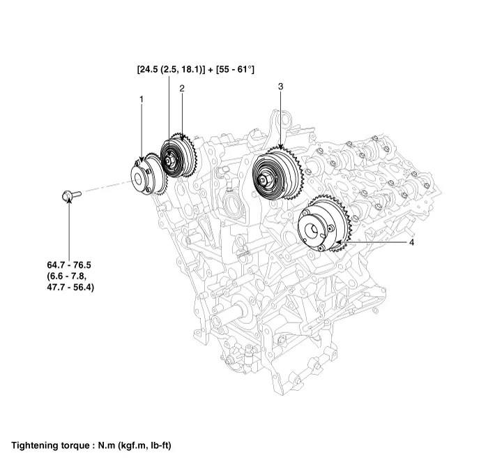
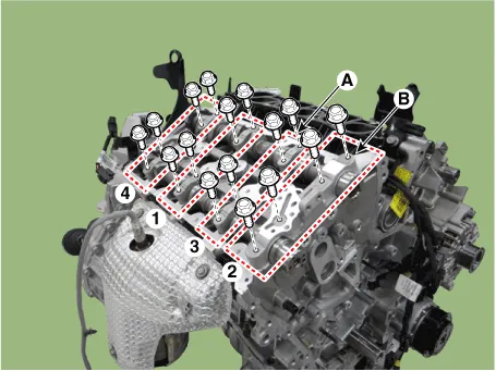
1. RH exhaust CVVT
2. RH intake CVVT
|
3. LH intake CVVT
4. LH exhaust CVVT
|
Repair procedures
| • |
Be careful not to damage the parts located under the vehicle
(floor under cover, fuel filter, fuel tank and canister) when
raising the vehicle using the lift.
(Refer to General Information - "Lift and Support Points")
|
|
LH CVVT & Camshaft
| 1. |
Set No.1 cylinder to TDC (Top dead center) on compression stroke.
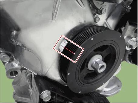
| (1) |
Turn the crankshaft damper pulley clockwise and align its groove
with the timing mark "T" of the lower timing chain cover.
|
| (2) |
Remove the LH cylinder head cover.
(Refer to Cylinder Head Assembly - "Cylinder Head Cover")
|
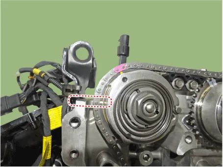
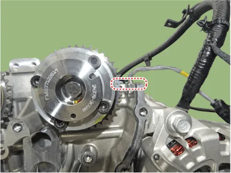
| (3) |
Check that the mark of the camshaft timing sprockets are in
straight line on the cylinder head surface as shown in the illustration.
If not, turn the crankshaft clockwise one revolution (360°).
[LH intake]
[LH exhaust]
[RH intake]
[RH exhaust]
|
|
| 2. |
Remove the timing chain.
(Refer to Timing System - "Timing Chain")
|
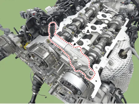
| 3. |
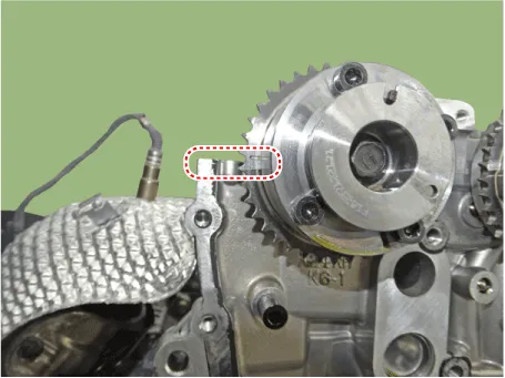
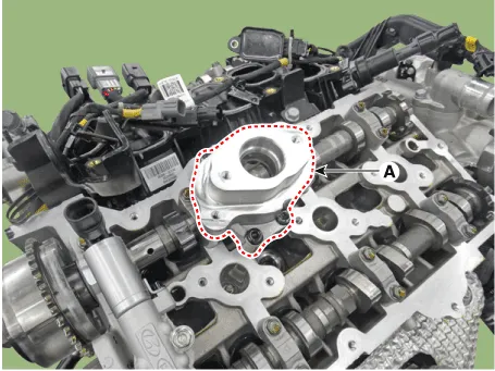
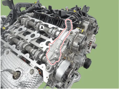
Remove the fuel pump bracket (A)
|
| 4. |
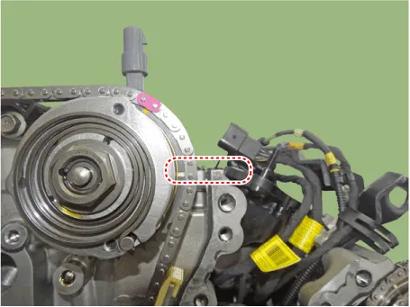
Remove the LH exhaust camshaft oil control valve (OCV) (A).

|
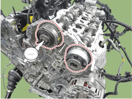
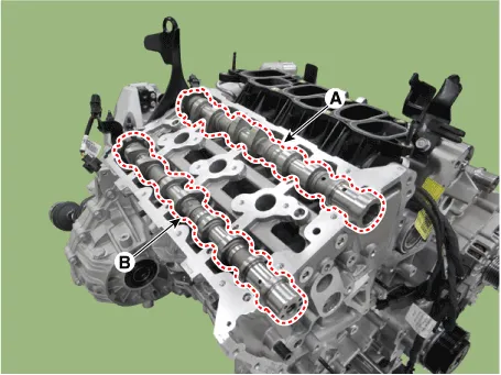
| 5. |
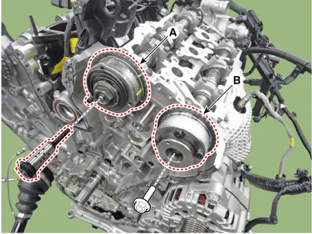
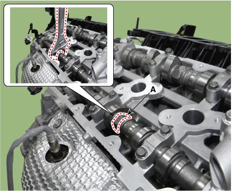
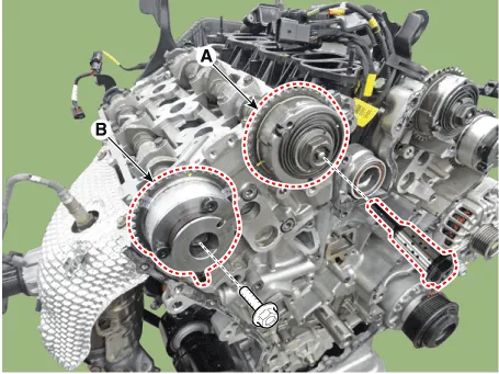
Remove the LH intake CVVT assembly (A) and exhaust CVVT assembly (B).
| •
|
To prevent impurities from entering intake OCV & center
bolt, wear rubber gloves.
|
| •
|
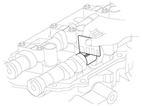
When removing the CVVT assembly bolt, place a wrench
at position (A) to prevent the camshaft from rotating.
|
|
|
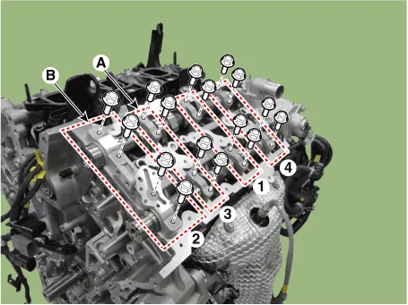
| 6. |
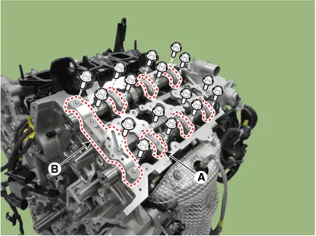
Remove the LH camshaft bearing cap (A) and thrust bearing cap (B).
|
| 7. |
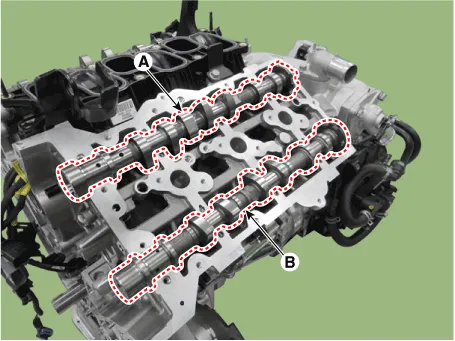
Remove the LH intake camshaft (A) and exhaust camshaft (B).
|
RH CVVT & Camshaft
| 1. |
Set No.1 cylinder to TDC (Top dead center) on compression stroke.
| (1) |
Turn the crankshaft damper pulley clockwise and align its groove
with the timing mark "T" of the lower timing chain cover.

|
| (2) |
Remove the RH cylinder head cover.
(Refer to Cylinder Head Assembly - "Cylinder Head Cover")
|
| (3) |
Check that the mark of the camshaft timing sprockets are in
straight line on the cylinder head surface as shown in the illustration.
If not, turn the crankshaft clockwise one revolution (360°).
[LH intake]

[LH exhaust]

[RH intake]

[RH exhaust]

|
|
| 2. |
Remove the timing chain.
(Refer to Timing System - "Timing Chain")
|
| 3. |
Remove the RH exhaust camshaft oil control valve (OCV) (A).

|
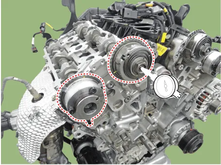
| 4. |
Remove the RH intake CVVT assembly (A) and exhaust CVVT assembly (B).

| •
|
To prevent impurities from entering intake OCV & center
bolt, wear rubber gloves.
|
| •
|
When removing the CVVT assembly bolt, place a wrench
at position (A) to prevent the camshaft from rotating.

|
|
|
| 5. |
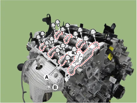
Remove the RH camshaft bearing cap (A) and thrust bearing cap (B).
|
| 6. |
Remove the RH intake camshaft (A) and exhaust camshaft (B).

|
Continuous Variable Valve Timing (CVVT) Assembly
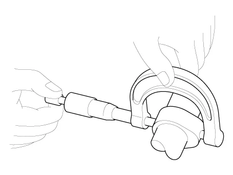
| 1. |
Inspect the exhaust CVVT for smooth rotation.
| (1) |
Clamp the camshaft using a vise. Be careful not to damage the
cam lobes and journals in the vise.
|
| (2) |
Check that the exhaust CVVT is locked by turning it clockwise
or counterclockwise. It must not rotate.
|
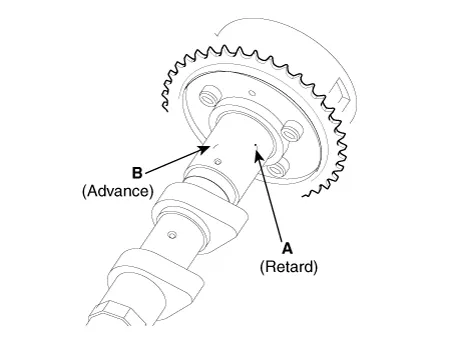
| (3) |
Intake CVVT : Seal one of the two advance holes in the camshaft
journal with tape.
Exhaust CVVT : Seal one of the two retard holes in the camshaft
journal with tape.
[Exhaust]
|
| (4) |
Exhaust CVVT : Apply approx. 150 kPa (1.5 kgf/cm², 21 psi) of
compressed air into the unsealed advance hole to release the
lock.
|
• |
Cover the oil paths with a piece of cloth when
applying compressed air to prevent oil from
spraying.
|
|
|
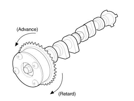
| (5) |
With compressed air applied, rotate the exhaust CVVT into the
retard direction (clockwise) and check that the CVVT turns smoothly.
|
Exhaust CVVT phasing range
25°± 0°30’ (from the most retarded position to the most
advanced position)
|
|
| (6) |
Rotate the exhaust CVVT into the most advanced position (counterclockwise)
and then check that the CVVT is locked.
|
|
Camshaft
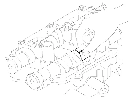
| 1. |
Inspect cam lobes.
Using a micrometer, measure the cam lobe height.
|
Cam height
[Standard value]
Intake : 47.2 mm (1.858 in.)
Exhaust : 45.8 mm (1.803 in.)
|
If the cam lobe height is below specification, replace the camshaft.
|
| 2. |
Inspect the camshaft journal clearance.
| (1) |
Clean the bearing caps and camshaft journals.
|
| (2) |
Place the camshafts on the cylinder head.
|
| (3) |
Lay a strip of plastigage across each of the camshaft journals.
|
| (4) |
Install the bearing cap (A) and thrust bearing cap (B) to the
specified torque.
|
Tightening torque
1st step : 5.8 N.m (0.6 kgf.m, 4.3 lb.ft)
2nd step : 9.8 - 11.8 N.m (1.0 - 1.2 kgf.m, 7.2 - 8.7
lb.ft)
|


|
• |
Do not turn the camshaft.
|
|
|
| (5) |
Remove the bearing caps.
|
| (6) |
Measure the plastigage at its widest point.
|
Bearing oil clearance
[Standard value]
Intake
No.1 journal : 0.037 - 0.067 mm (0.0015 - 0.0026 in.)
No.2,3,4 journal : 0.030 - 0.067 mm (0.0012 - 0.0026
in.)
Exhaust
No.1 journal : 0.027 - 0.057 mm (0.0010 - 0.0022 in.)
No.2,3,4 journal : 0.030 - 0.067 mm (0.0012 - 0.0026
in.)
|
| •
|
If the oil clearance is greater than specification,
replace the camshaft.
|
| •
|
If the oil clearance is still over the specification
after replacing the camshaft, replace the bearing caps
and cylinder head as an assembly.
|
|
| (7) |
Completely remove the plastigage.
|
| (8) |
Remove the camshafts.
|
|
| 3. |
Inspect the camshaft end play.
| (1) |
Install the camshafts.
|
| (2) |
Install the bearing cap (A) and thrust bearing cap (B) to the
specified torque.
|
Tightening torque
1st step : 5.8 N.m (0.6 kgf.m, 4.31 lb.ft)
2st step : 9.8 N.m (1.0 - 1.2 kgf.m, 7.2 - 8.7 lb.ft)
|

|
| (3) |
Using a dial indicator, measure the end play while moving the
camshaft back and forth.
|
Camshaft end play
[Standard value] :
Intake : 0.04 - 0.18 mm (0.0016 - 0.0071 in.)
Exhaust : 0.02 - 0.18 mm (0.0008 - 0.0071 in.)
|
| •
|
If the end play is greater than specification, replace
the camshaft.
|
| •
|
If the end play is still over the specification after
replacing the camshaft, replace the bearing caps and
cylinder head as an assembly.
|
|
| (4) |
Remove the camshafts.
|
|
| • |
Apply a light coat of engine oil on camshaft journals.
|
| • |
Assemble the key groove of camshaft rear side to the same level
of head top surface.
|
| • |
Be cautious not to damage the right and left banks, and intake
and exhaust sides when assembling.
|
|
Intake camshaft
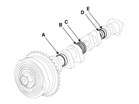
As for camshaft identification (A, B, C, D, E), refer to the table below.
Displacement
|
Outer diameter
|
LH
|
RH
|
Intake camshaft
|
-
|
A : 30 mm (1.1811 in.)
|
B : 27 mm (1.0630 in.)
|
C : 30 mm (1.1811 in.)
|
D : 30 mm (1.1811 in.)
|
E : 30 mm (1.1811 in.)
|
Exhaust camshaft
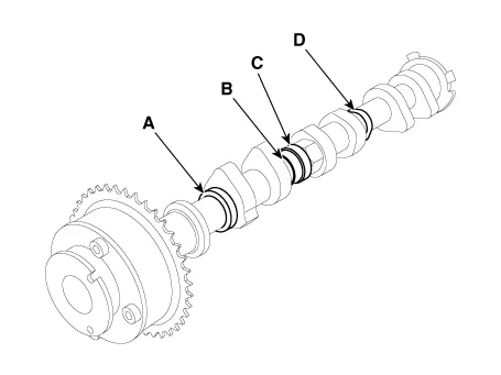
As for camshaft identification (A, B, C, D), refer to the table below.
Displacement
|
Outer diameter
|
LH
|
RH
|
Exhaust camshaft
|
A : 27 mm (1.0630 in.)
|
A : 27 mm (1.0630 in.)
|
B : 27 mm (1.0630 in.)
|
B : 27 mm (1.0630 in.)
|
C : 30 mm (1.1811 in.)
|
C : 30 mm (1.1811 in.)
|
D : 27 mm (1.0630 in.)
|
D : 30 mm (1.1811 in.)
|
LH CVVT & Camshaft
| 1. |
Install the LH intake camshaft (A) and exhaust camshaft (B).

|
| 2. |
Install the LH camshaft bearing cap (A) and thrust bearing cap (B) with
specified torque.
|
Tightening torque
1st step :
5.8 N.m (0.6 kgf.m, 4.3 lb.ft)
2nd step :
9.8 - 11.8 N.m (1.0 - 1.2 kgf.m, 7.2 - 8.7 lb.ft)
|

| •
|
Be sure to install the thrust bearing cap bolts and
the bearing cap bolts in the correct place.
|
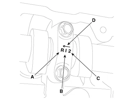
| •
|
Be cautious not to damage the right and left banks,
and intake and exhaust sides when assembling.

A : L (LH), R (RH)
B : I (Intake), E (Exhaust)
C : Journal number
D : Front mark
|
| •
|
Rotate the crankshaft until the pistons are located
10mm (0.3937in.) below the top of cylinder block so
that it doesn't come into contact with the valves.
|
|
|
| 3. |
Install the LH intake CVVT assembly (A) and exhaust CVVT assembly (B).
|
Tightening torque
Intake : 24.5 N.m (2.5 kgf.m, 18.1 lb.ft) + 55 - 61°
Exhaust : 64.7 - 76.5 N.m (6.6 - 7.8 kgf.m, 47.7 - 56.4 lb.ft)
|

| •
|
To prevent impurities from entering intake OCV & center
bolt, wear rubber gloves.
|
| •
|
When installing intake OCV & center bolt, temporarily
install by hand, and then fully install by using a tool.
|
| •
|
When installing intake OCV & center bolt, install to
the specified tightening torque.
|
| •
|
Do not use any dropped intake OCV & center bolt.
|
| •
|
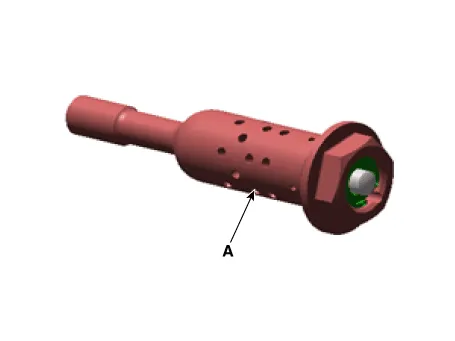
When installing intake CVVT, apply engine oil on cross
section (A) of OCV.

|
| •
|
When installing CVVT assembly bolt, hold A section of
camshaft with a wrench.
|
| •
|
Be careful not to damage cylinder head and camshaft.

|
| •
|
Install camshaft-inlet to dowel pin of CVVT assembly.
When doing this, be careful not to install on the oil
hole of camshaft-inlet.
|
| •
|
Hold the hexagonal head wrench portion of the camshaft
with a vise, and install the bolt and CVVT assembly.
|
| •
|
Do not rotate CVVT assembly when installing the camshaft
to the dowel pin of CVVT assembly.
|
|
|
| 4. |
Install the LH exhaust camshaft oil control valve (OCV) (A).
|
Tightening torque :
9.8 - 11.8 N.m (1.0 - 1.2 kgf.m, 7.2 - 8.7 lb.ft)
|
|
| 5. |
Install the fuel pump bracket (A).
|
Tightening torque :
18.6 - 23.5 N.m (1.9 - 2.4 kgf.m, 13.7 - 17.4 lb.ft)
|

|
| 6. |
Install in the reverse order of removal.
|
RH CVVT & Camshaft
| 1. |
Install the RH intake camshaft (A) and exhaust camshaft (B).
|
| 2. |
Install the RH camshaft bearing cap (A) and thrust bearing cap (B) to
the specified torque.
|
Tightening torque
1st step : 5.8 N.m (0.6 kgf.m, 4.3 lb.ft)
2nd step :9.8 - 11.8 N.m (1.0 - 1.2 kgf.m, 7.2 - 8.7 lb.ft)
|
| •
|
Be sure to install the thrust bearing cap bolts and
the bearing cap bolts in the correct place.
|
| •
|
Be cautious not to damage the right and left banks,
and intake and exhaust sides when assembling.
A : L (LH), R (RH)
B : I (Intake), E (Exhaust)
C : Journal number
D : Front mark
|
| •
|
Rotate the crankshaft until the pistons are located
10mm (0.3937in.) below the top of cylinder block so
that it doesn't come into contact with the valves.
|
|
|
| 3. |
Install the RH intake CVVT assembly (A) and exhaust CVVT assembly (B).
|
Tightening torque
Intake : 24.5 N.m (2.5 kgf.m, 18.1 lb.ft) + 55 - 61°
Exhaust : 64.7 - 76.5 N.m (6.6 - 7.8 kgf.m, 47.7 - 56.4 lb.ft)
|
| •
|
To prevent impurities from entering intake OCV & center
bolt, wear rubber gloves.
|
| •
|
When installing intake OCV & center bolt, temporarily
install by hand, and then fully install by using a tool.
|
| •
|
When installing intake OCV & center bolt, install to
the specified tightening torque.
|
| •
|
Do not use any dropped intake OCV & center bolt.
|
| •
|
When installing intake CVVT, apply engine oil on cross
section (A) of OCV.
|
| •
|
When installing CVVT assembly bolt, hold A section of
camshaft with a wrench.
|
| •
|
Be careful not to damage cylinder head and camshaft.

|
| •
|
Install camshaft-inlet to dowel pin of CVVT assembly.
When doing this, be careful not to install on the oil
hole of camshaft-inlet.
|
| •
|
Hold the hexagonal head wrench portion of the camshaft
with a vise, and install the bolt and CVVT assembly.
|
| •
|
Do not rotate CVVT assembly when installing the camshaft
to the dowel pin of CVVT assembly.
|
|
|
| 4. |
Install the RH exhaust camshaft oil control valve (OCV) (A).
|
Tightening torque :
9.8 - 11.8 N.m (1.0 - 1.2 kgf.m, 7.2 - 8.7 lb.ft)
|
|
| 5. |
Install in the reverse order of removal.
|
Components and components location
Components
1. LH cylinder head cover
2. LH cylinder head cover gasket
3. LH exhaust CVVT OCV cap
4.
Components and components location
Components
1. RH intake camshaft OCV
2. Camshaft thrust bearing cap
3. Camshaft bearing cap
4.
Other information:
System Block Diagram
Component Parts And Function Outline
Component part
Function
Vehicle-speed sensor, ESP/ABS Control Module
Converts vehicle speed to pulse.
ECM
Receives signals from sensor and control switches.
Components and components location
Components
1. Remote control switch (Audio
swtich)
2. Remote control switch (Cruise
control switch)
Schematic diagrams
Circuit Diagram
Repair procedures
Removal
1.


