Hyundai Palisade (LX2): Cylinder Head Assembly / Cylinder Head Cover
Components and components location
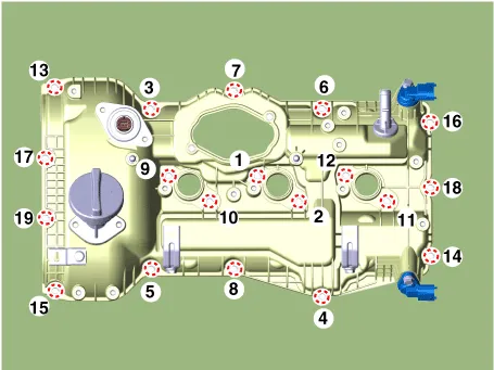
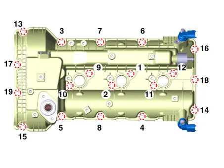
| Components |
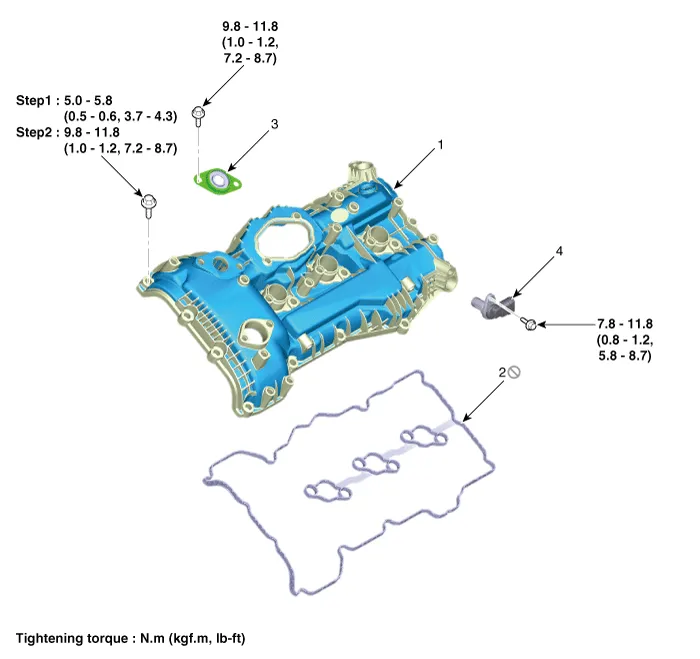
| 1. LH cylinder head cover 2. LH cylinder head cover gasket |
3. LH exhaust CVVT OCV cap 4. Camshaft position sensor (CMPS) |
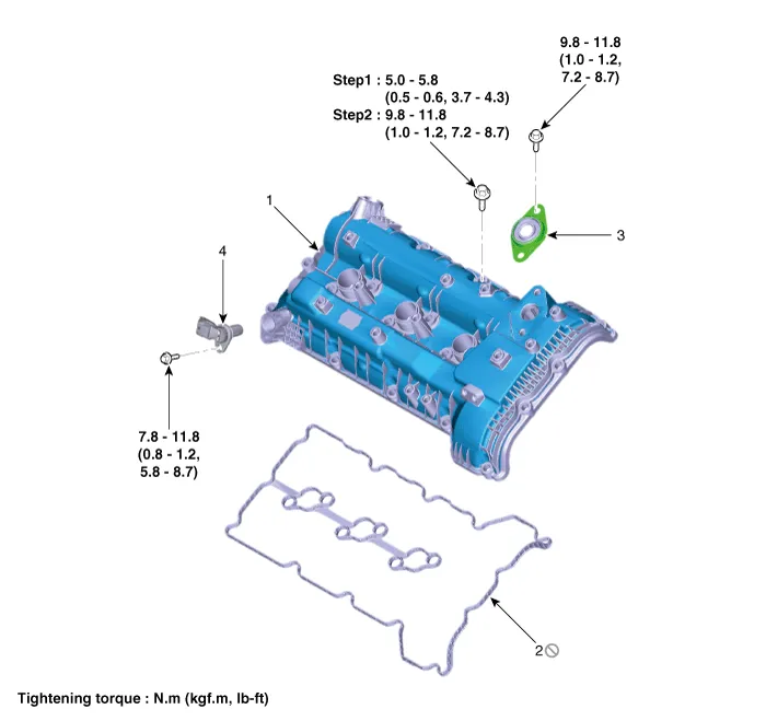
| 1. RH cylinder head cover 2. RH cylinder head cover gasket |
3. RH exhaust CVVT OCV cap 4. Camshaft position sensor (CMPS) |
Repair procedures
| Removal |
| 1. |
Remove the engine cover.
(Refer to Engine And Transaxle Assembly - "Engine Cover")
|
| 2. |
Remove the air cleaner assembly.
(Refer to Intake And Exhaust System - "Air Cleaner")
|
| 3. |
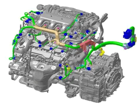
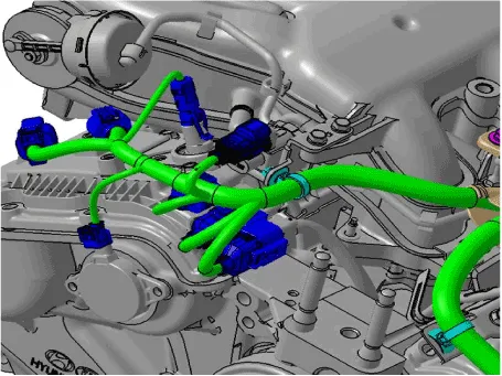
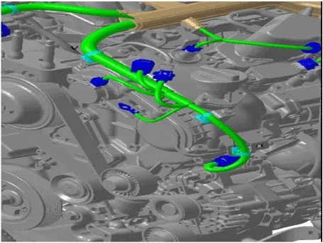
Disconnect the control wiring harness connectors and fasteners and remove
the wiring harness protectors from the LH cylinder head cover.
|

| 4. |
Remove the LH ignition coils.
(Refer to Engine Electrical System - "Ignition Coil")
|
| 5. |
Remove the high pressure fuel pump.
(Refer to Engine Control / Fuel System - "High Pressure Fuel Pump")
|
| 6. |
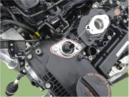
Remove the LH exhaust CVVT oil control valve cap (A).
|
| 7. |
Remove the oil level gauge rod mounting bolt.
(Refer to Lubrication System - "Oil Level Gauge & Pipe")
|
| 8. |
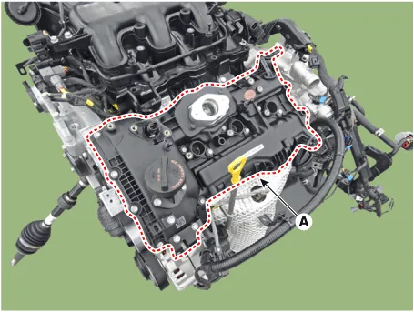
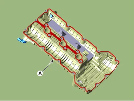
Remove the LH cylinder head cover (A) and gasket.
|

| 9. |
Remove the engine cover.
(Refer to Engine And Transmission Assembly - "Engine Cover")
|
| 10. |
Remove the air cleaner assembly.
(Refer to Intake And Exhaust System - "Air Cleaner")
|
| 11. |
Disconnect the control wiring harness connectors and fasteners and remove
the wiring harness protectors from the RH cylinder head cover.
|


| 12. |
Remove the surge tank.
(Refer to Intake And Exhaust System - "Surge Tank")
|
| 13. |
Remove the RH ignition coils.
(Refer to Engine Electrical System - "Ignition Coil")
|
| 14. |
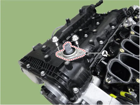
Remove the RH exhaust CVVT oil control valve cap (A).
|
| 15. |
Remove the RH cylinder head cover (A) and gasket.
|


| Installation |
| 1. |
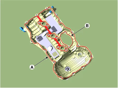
Install the new cylinder head cover gasket (A) and high pressure fuel
pump gasket (B).
|
| 2. |
Install the LH cylinder head cover.
|


| 3. |
Install the LH exhaust CVVT oil control valve cap (A).
|


| 4. |
Install in the reverse order of removal.
|
| 1. |
Install the new cylinder head cover gasket (A).
|
| 2. |
Install the RH cylinder head cover.
|


| 3. |
Install the RH exhaust CVVT oil control valve cap (A).
|


| 4. |
Install in the reverse order of removal.
|
Valve Clearance Inspection and Adjustment (MLA) • Inspect and adjust the valve clearance with engine cold (engine coolant temperature : 20°C (68°F)) and cylinder head installed to the cylinder block.
Components and components location Components 1. RH exhaust CVVT 2. RH intake CVVT 3. LH intake CVVT 4. LH exhaust CVVT Repair procedures Removal • Be careful not to damage the parts located under the vehicle (floor under cover, fuel filter, fuel tank and canister) when raising the vehicle using the lift.
Other information:
Hyundai Palisade (LX2) 2020-2026 Service Manual: Description and operation
Description The smart cruise control system allows a driver to program the vehicle to control the speed and following distance by detecting the vehicle ahead without depressing the brake pedal or the accelerator pedal. 1.
Hyundai Palisade (LX2) 2020-2026 Service Manual: Specifications
Categories
- Manuals Home
- Hyundai Palisade Owners Manual
- Hyundai Palisade Service Manual
- Body Electrical System
- Scheduled maintenance services
- Body (Interior and Exterior)
- New on site
- Most important about car
