Hyundai Palisade (LX2): Timing System / Crankshaft Damper Pulley
Repair procedures
| Removal and Installation |
|

| 1. |
Remove the engine room under cover.
(Refer to Engine and Transaxle Assembly - "Engine Room Under Cover")
|
| 2. |
Remove the RH side front wheel.
(Refer to Suspension System - "Wheel")
|
| 3. |
Remove the drive belt.
(Refer to Timing System - "Drive Belt")
|
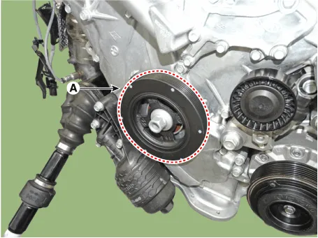
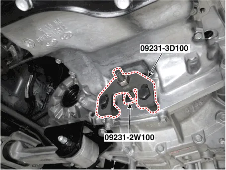
| 4. |
Remove the crankshaft damper pulley (A).
|

| 5. |
Install in the reverse order of removal.
|
Repair procedures Removal and Installation • Be careful not to damage the parts located under the vehicle (floor under cover, fuel filter, fuel tank and canister) when raising the vehicle using the lift.
Repair procedures Removal • Be careful not to damage the parts located under the vehicle (floor under cover, fuel filter, fuel tank and canister) when raising the vehicle using the lift.
Other information:
Hyundai Palisade (LX2) 2020-2026 Service Manual: Heater Core
Repair procedures Replacement 1. Disconnect the negative (-) battery terminal. 2. Remove the heater and blower assembly. (Refer to Heater - "Heater Unit") 3.
Hyundai Palisade (LX2) 2020-2026 Service Manual: Warning Indicator
Components and components location Components 1. Warning indicator 2. SVM camera Repair procedures Removal 1. Disconnect the negative (-) battery terminal. 2.
Categories
- Manuals Home
- Hyundai Palisade Owners Manual
- Hyundai Palisade Service Manual
- Automatic Transaxle Fluid (ATF)
- Resetting the Driver's Seat Memory System
- Scheduled maintenance services
- New on site
- Most important about car
