Hyundai Palisade (LX2): Emission Control System / Components and components location
Hyundai Palisade (LX2) 2020-2026 Service Manual / Emission Control System / Components and components location
| Components Location |
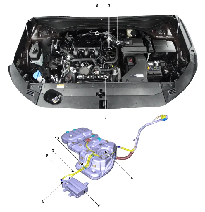
| 1. PCV Valve 2. Canister 3. Purge control solenoid valve (PCSV) 4. Fuel level sensor (FLS) 5. Fuel tank air filter |
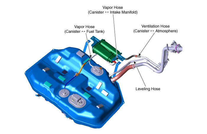
6. Catalytic converter (WCC) 7. Catalytic converter (UCC) 8. Vapor hose (Canister ↔ Intake Manifold ) 9. Vapor Hose (Canister ↔ Fuel Tank) 10. Ventilation hose (Canister ↔ Atmosphere) |
|
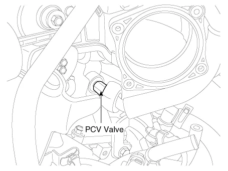
1. PCV valve |
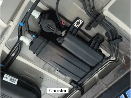
2. Canister |
|
|
|
|
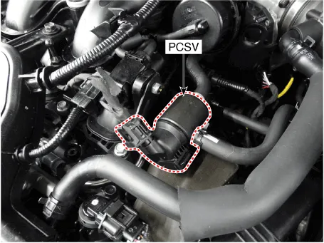
3. Purge Control Solenoid Valve (PCSV) |
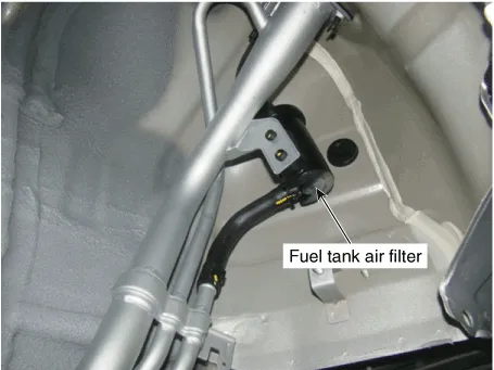
4. Fuel Tank Air Filter |
|
|
|
|
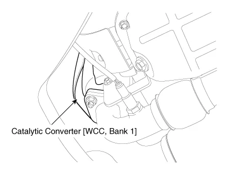
5. Catalytic Converter (WCC, Bank 1) |
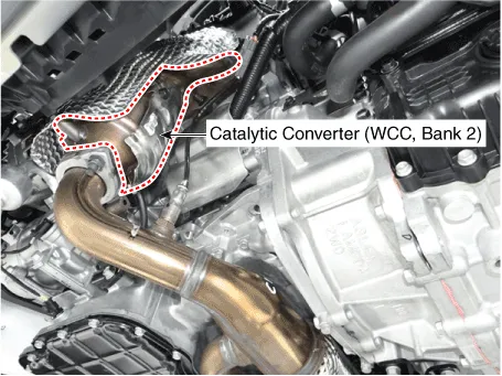
5. Catalytic Converter (WCC, Bank 2) |
|
|
|
|
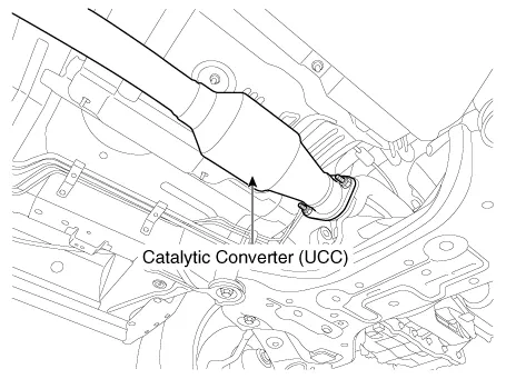
6. Catalytic Converter (UCC) |
|
|
|
|
|
7. Leveling Hose 8. Vapor Hose (Canister ↔ Intake Manifold) 9. Vapor Hose (Canister ↔ Fuel Tank) 10. Ventilation Hose (Canister ↔ Atmosphere) |
|
|
|
|
Schematic Diagram
Other information:
Hyundai Palisade (LX2) 2020-2026 Service Manual: Rear Evaporator Core
Repair procedures Replacement 1. Remove the rear heater & A/C unit. (Refer to Rear Heater - "Rear Heater Unit") 2. Loosen the mounting screws, remove the rear heater & A/C unit cover (A) and evaporator core (B).
Hyundai Palisade (LX2) 2020-2026 Service Manual: Schematic diagrams
System Block Diagram Component Parts And Function Outline Component part Function Vehicle-speed sensor, ESP/ABS Control Module Converts vehicle speed to pulse. ECM Receives signals from sensor and control switches.
Categories
- Manuals Home
- Hyundai Palisade Owners Manual
- Hyundai Palisade Service Manual
- Resetting the Driver's Seat Memory System
- Removing and Storing the Spare Tire
- Emergency liftgate safety release
- New on site
- Most important about car

Copyright © 2026 www.hpalisadelx.com - 0.016