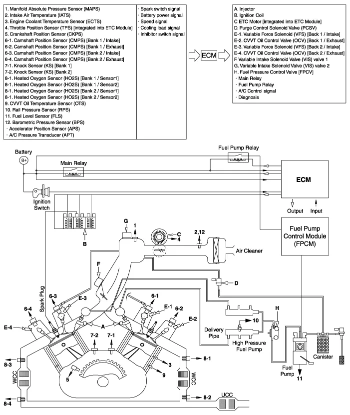
Hyundai Palisade (LX2): Emission Control System / Schematic diagrams
| Schematic Diagram |
Troubleshooting Symptom Suspected area Engine does not start or struggles to start Vapor hose damaged or disconnected Engine struggles to start Malfunctioning Purge Control Solenoid Valve Rough idle or engine stalls Vapor hose damaged or disconnected Malfunctioning PCV valve Rough idle Malfunctioning Evaporative Emission Control System Excessive oil consumption Positive crankcase ventilation line clogged
Components Location 1. PCV Valve 2. Canister 3. Purge control solenoid valve (PCSV) 4. Fuel level sensor (FLS) 5.
Other information:
Hyundai Palisade (LX2) 2020-2026 Service Manual: Mode Control Actuator
Description and operation Description The mode control actuator is located at the heater unit. It adjusts the position of the mode door by operating the mode control actuator based on the signal of the A/C control unit. Pressing the mode select switch makes the mode control actuator shift in order of Vent → Bi-Level →
Hyundai Palisade (LX2) 2020-2026 Service Manual: Repair procedures
Inspection Tolerance Compensation Tolerance compensation compensates for the error margins of around view video that occur due to the installation tolerance when the four cameras that comprise the SVM system are installed. You must carry out tolerance compensation if you do any of the following.
Categories
- Manuals Home
- Hyundai Palisade Owners Manual
- Hyundai Palisade Service Manual
- Automatic Transaxle Fluid (ATF)
- Body (Interior and Exterior)
- Troubleshooting
- New on site
- Most important about car
