Hyundai Palisade (LX2): Automatic Transaxle System / Automatic Transaxle Fluid (ATF)
Components and components location
| Components Location |
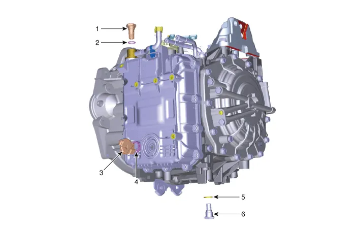
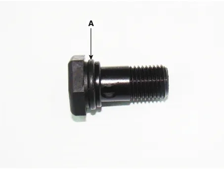
| 1. ATF Injection plug (Eyebolt) 2. ATF injection plug gasket 3. ATF level check plug |
4. ATF level check plug gasket 5. Drain plug gasket 6. Drain plug |
Repair procedures
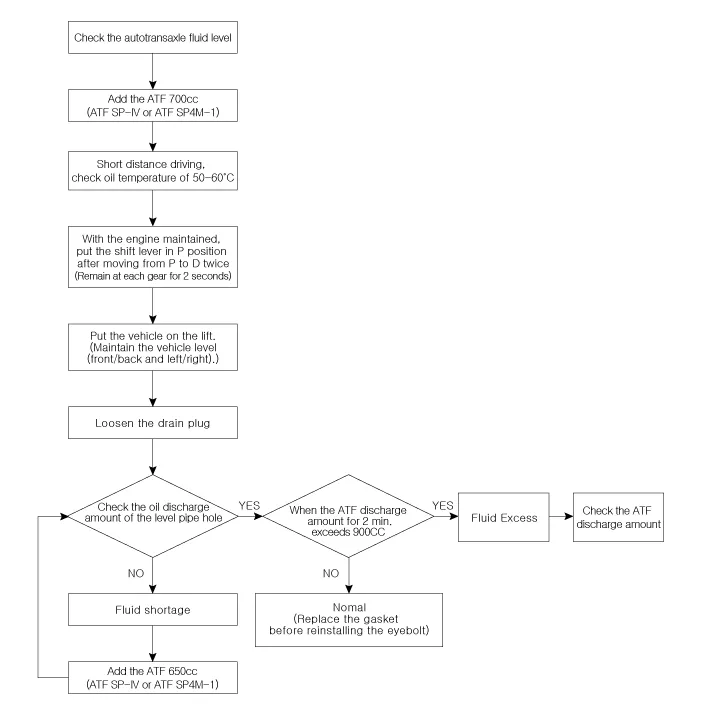
| Automatic Transaxle Fluid (ATF) Level Check |
|

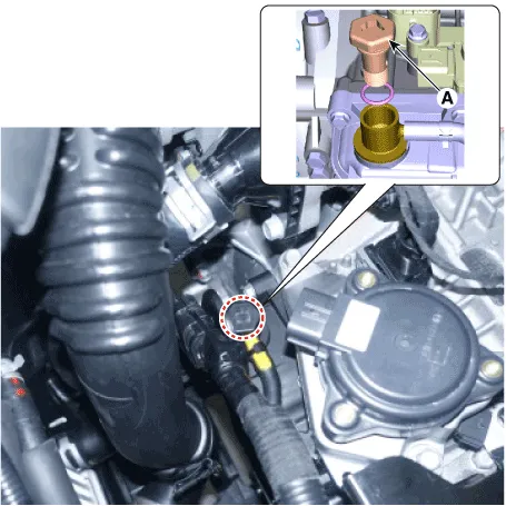
| 1. |
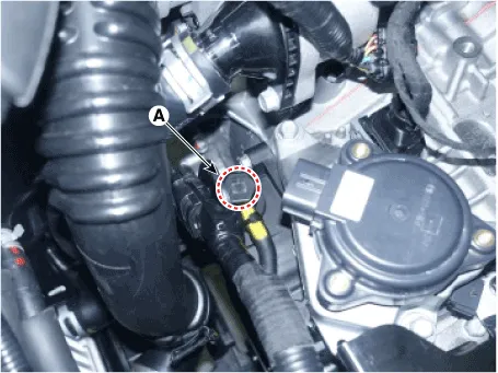
Remove the eyebolt (A).
|
| 2. |
Add ATF SP-IV or SP4M-1 700cc to the ATF injection hole (A).
|
| 3. |
Start the engine.
(Don’t step on brake and accelerator simultaneously.)
|
| 4. |
Confirm that the temperature of the automatic transaxle oil temperature
sensor is 50 - 60°C (122 - 140°F) with the diagnostic tool.
|
| 5. |
Shift the select lever slowly from “P” to “D”, then “D” to “P” and repeat
one more at idle.
|

| 6. |
Raise the vehicle, and make sure it is securely supported.
|
| 7. |
Remove the under cover.
(Refer to Engine Mechanical System - "Engine Room Under Cover")
|
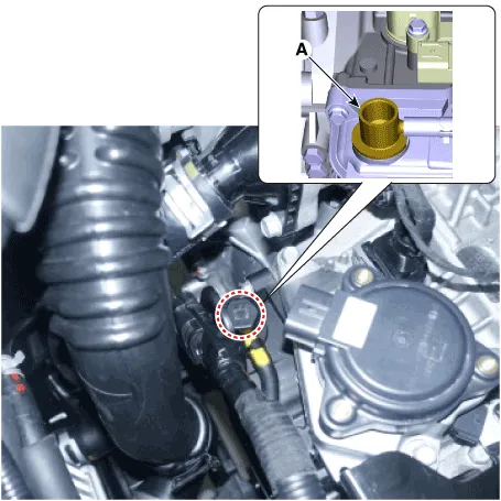
| 8. |
Remove the ATF level check plug (A) from the valve body cover.
|
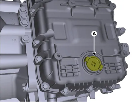

| 9. |
If the ATF flows out of the overflow plug in thin steady stream, the
ATF level is correct.
Then finish the procedure and tighten the ATF level check plug.
|


| 10. |
Install the under cover.
(Refer to Engine Mechanical System - "Engine Room Under Cover")
|
| 11. |
Put down the vehicle with the lift and then tighten the eyebolt.
|


| Replacement |
ATF of 8 speed automatic transaxle doesn’t be replaced. But, if the
vehicle is severe use or business use, replace ATF every 60,000 miles
for severe usage.
Severe usage is defined as
|

| 1. |
Lift the vehicle, and then remove the under cover.
(Refer to Engine Mechanical System - "Engine Room Under Cover")
|
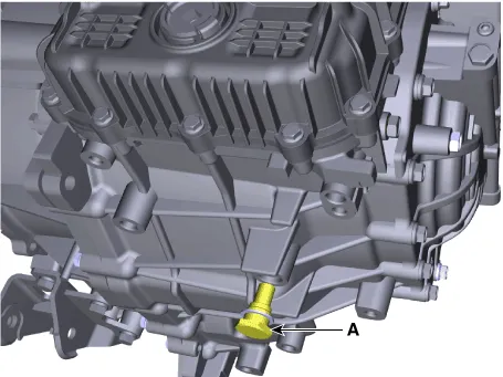
| 2. |
Remove the drain plug (A) and reinstall the drain plug after draining
ATF totally.
|

| 3. |
Put down the vehicle with the lift and then remove the eyebolt (A).
|
| 4. |
Fill the ATF about 5 liters to the injection hole.
|
| 5. |
Check the ATF level.
(Refer to Automatic Transaxle System - "Automatic Transaxle Fluid (ATF)")
|
| 6. |
Then finish check the ATF level procedure and install the under cover.
(Refer to Engine Mechanical System - "Engine Room Under Cover")
|
| 7. |
Put down the vehicle with the lift and then tighten the eyebolt.
|

Repair procedures Removal • Carefully install the clamp not to damage the hose.
Other information:
Hyundai Palisade (LX2) 2020-2026 Service Manual: A/C Pressure Transducer
Description and operation Description The A/C Pressure Transducer (APT) converts the pressure value of high pressure line into voltage value after measuring it. By converted voltage value, engine ECU controls the cooling fan by operating it high speed or low speed.
Hyundai Palisade (LX2) 2020-2026 Service Manual: Schematic diagrams
Trouble Symptom Charts Component Parts and Function Outline Component part Function Cruise Control Switch Input the set speed and distance to the SCC ECU. Instrument Cluster Display various information inputted from SCC.
Categories
- Manuals Home
- Hyundai Palisade Owners Manual
- Hyundai Palisade Service Manual
- Body (Interior and Exterior)
- Engine Mechanical System
- Resetting the Driver's Seat Memory System
- New on site
- Most important about car
