Hyundai Palisade (LX2): Engine Control System / Accelerator Position Sensor (APS)
Description and operation
| Description |

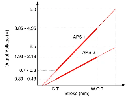
Specifications
| Specification |
|
Accelerator Position |
Output Voltage (V) [Vref = 5V] |
|
|
APS1 |
APS2 |
|
|
C.T |
0.7 - 0.8 |
0.33 - 0.43 |
|
W.O.T |
3.85 - 4.35 |
1.93 - 2.18 |
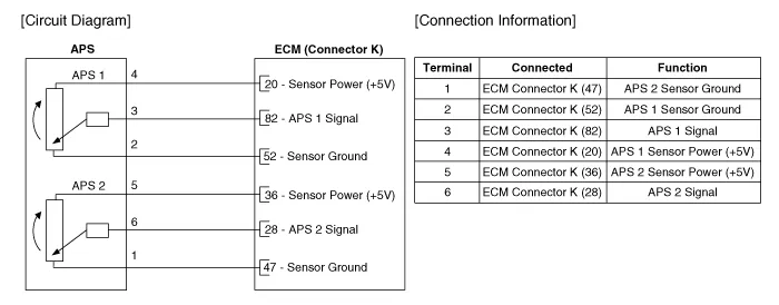
Schematic diagrams
| Circuit Diagram |
Repair procedures
| Inspection |
| 1. |
Connect the diagnostic tool on the Data Link Connector (DLC).
|
| 2. |
Switch "ON" the ignition.
|
| 3. |
Measure the output voltage of the APS 1 and 2 at C.T and W.O.T.
|
|||||||||||
| Removal |
| 1. |
Switch "OFF" the ignition and disconnect the negative (-) battery terminal.
|
| 2. |
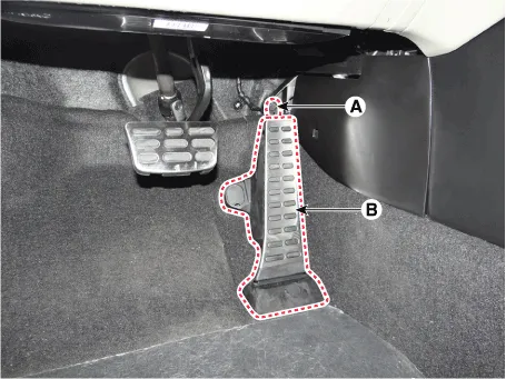
Disconnect the accelerator position sensor connector (A).
|
| 3. |
Remove the accelerator position sensor (B) after loosening the mounting
bolts.
|
| Installation |
| 1. |
Install in the reverse order of removal.
|
Description and operation Description Continuous Variable Valve Timing (CVVT) system advances or retards the valve timing of the intake and exhaust valve in accordance with the ECM control signal which is calculated by the engine speed and load.
Description and operation Description Based on information from various sensors, the ECM can calculate the fuel amount to be injected.
Other information:
Hyundai Palisade (LX2) 2020-2026 Service Manual: Front View Camera Unit
Schematic diagrams Circuit Diagram Repair procedures Removal 1. Disconnect the negative (-) battery terminal. 2. Remove the inside rear view mirror cover (A) and rain sensor cover (B).
Hyundai Palisade (LX2) 2020-2026 Service Manual: Schematic diagrams
System Block Diagram Component Parts And Function Outline Component part Function Vehicle-speed sensor, ESP/ABS Control Module Converts vehicle speed to pulse. ECM Receives signals from sensor and control switches.
Categories
- Manuals Home
- Hyundai Palisade Owners Manual
- Hyundai Palisade Service Manual
- Engine Mechanical System
- Maintenance
- Scheduled maintenance services
- New on site
- Most important about car
