Hyundai Palisade (LX2): Windshield Wiper/Washer / Windshield Wiper-Washer Switch
Repair procedures
| Removal |
| 1. |
Disconnect the negative (-) battery terminal.
|
| 2. |
Remove the steering wheel.
(Refer to Steering System - "Steering Wheel")
|
| 3. |
Remove the steering columm shround.
(Refer to Steering System - "Steering Columm Shround panel")
|
| 4. |
Remove the clock spring.
(Refer to Restraint - "Driver Airbag(DAB) and Clock Spring")
|
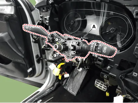
| 5. |
Remove the multifunction connector (A).
|

| 6. |
Remove the multifunction switch (A) after loosening the mounting screws
(2EA).
|
| Installation |
| 1. |
Install the multifunction switch after connecting the connector.
|
| 2. |
Install the clock spring and steering.
|
| 3. |
Install the upper and lower shroud.
|
| 4. |
Install the steering wheel.
|
| Inspection |
| 1. |
Check for continuity between the terminals in each switch position as
shown below.
|

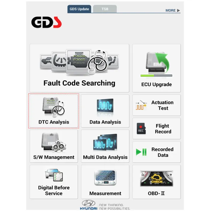
| 1. |
In the body electrical system, failure can be quickly diagnosed by using
the vehicle diagnostic system (Diagnostic tool).
The diagnostic system (Diagnostic tool) provides the following information.
|
| 2. |
If diagnose the vehicle by Diagnostic tool, select "DTC Analysis" and
"Vehicle".
|
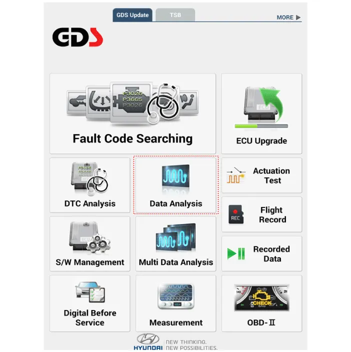
| 3. |
If check current status, select the "Data Analysis" .
|
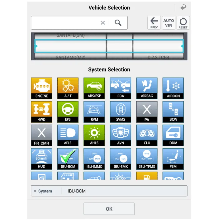
| 4. |
Select the 'IBU_BCM' to search the current state of the input/output
data.
|

Component Location 1. Windshield wiper arm & blade 2. Wiper & washer switch 3. Windshield washer hose 4. Windshield wiper motor & linkage 5.
Components and components location Component Location 1. Cap 2. Nut 3. Wiper arm & blade 4. Cowl top cover 5.
Other information:
Hyundai Palisade (LX2) 2020-2026 Service Manual: Repair procedures
Refrigerant System Service Basics (R-134a) Refrigerant Recovery Use only service equipment that is U.L-listed and is certified to meet the requirements of SAE J2210 to remove HFC-134a(R-134a) from the air conditioning system.
Hyundai Palisade (LX2) 2020-2026 Service Manual: In-car Sensor
Description and operation Description The In-car air temperature sensor is built in the heater & A/C control unit. The sensor consists of a thermistor that measures the inside temperature. The signal decided by the resistance value that changes in accordance with perceived inside temperature, is delivered to heater co
Categories
- Manuals Home
- Hyundai Palisade Owners Manual
- Hyundai Palisade Service Manual
- Emergency liftgate safety release
- How to reset the power liftgate
- Electrochromatic Mirror (ECM) with homelink system
- New on site
- Most important about car
