Hyundai Palisade (LX2): Front Suspension System / Sub Frame
Repair procedures
| Removal |
| 1. |
Turn the ignition switch OFF and disconnect the battery negative (-)
cable.
|
| 2. |
Turn the steering wheel so that the front wheels are placed in the straight
ahead position.
|
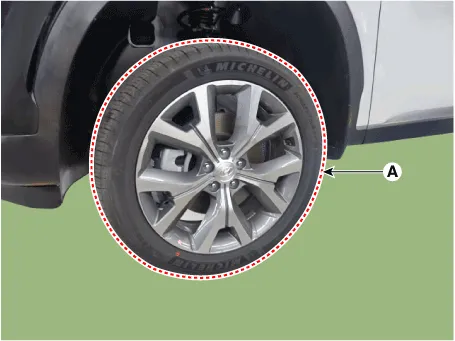
| 3. |
Remove the front wheel and tire (A) from front hub.
|

| 4. |
Disconnect the stabilizer link with the front strut assembly after loosening
the nut (A).
|

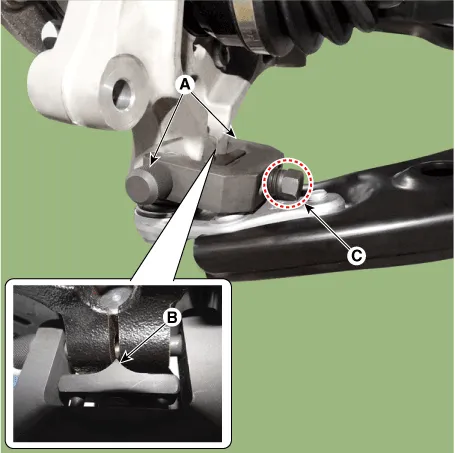
| 5. |
Remove the tie rod end ball joint.
|
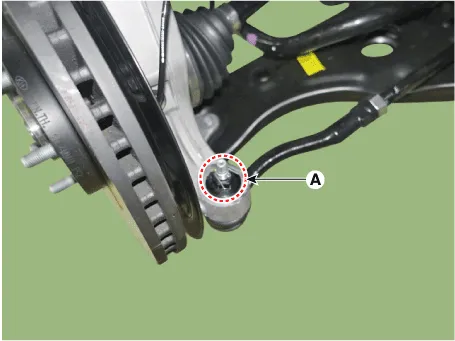
| 6. |
Remove the split pin and nut (A).
|
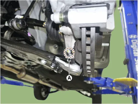
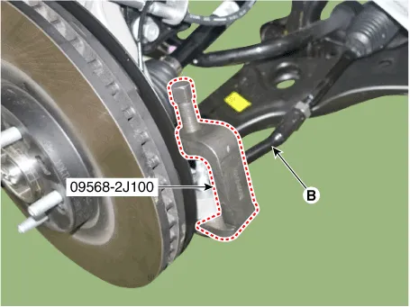
| 7. |
Remove the lower arm from the knuckle by using the SST (09568-4R100).
|
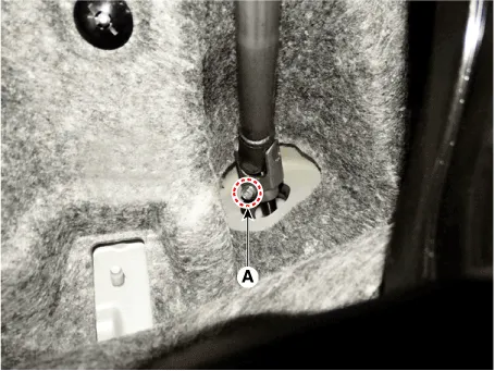
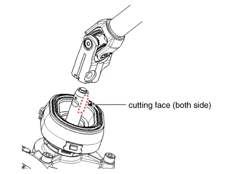
| 8. |
Loosen the bolt (A) and then disconnect the universal joint assembly
from the pinion of the steering gear box.
|

| 9. |
Remove the under cover.
(Refer to Engine Mechanical System - "Engine Room Under Cover")
|
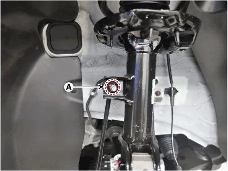
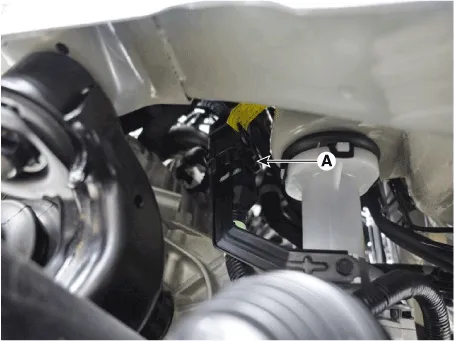
| 10. |
Disconnect the R-MDPS main connector (A). [R-MDPS Type only]
|
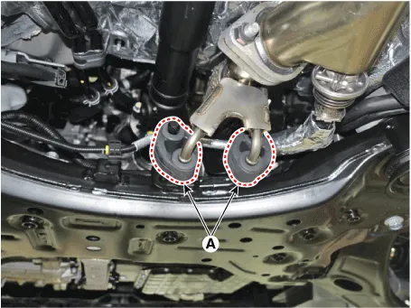
| 11. |
Remove the muffler rubber hanger (A).
|
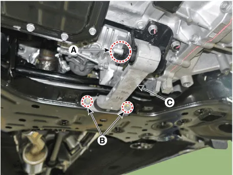
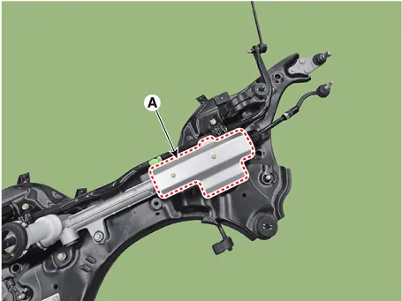
| 12. |
Remove the roll rod bracket (C) by loosening the bolt (A), (B).
|
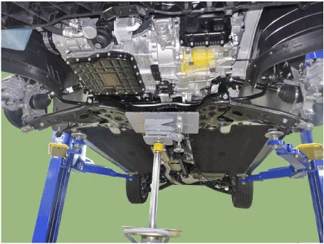
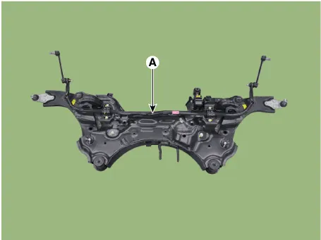
| 13. |
Remove the subframe by loosening the mounting bolts and nuts.
|

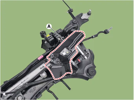
| 14. |
Remove the heated protector (A).
[C-MDPS]
[R-MDPS]
|
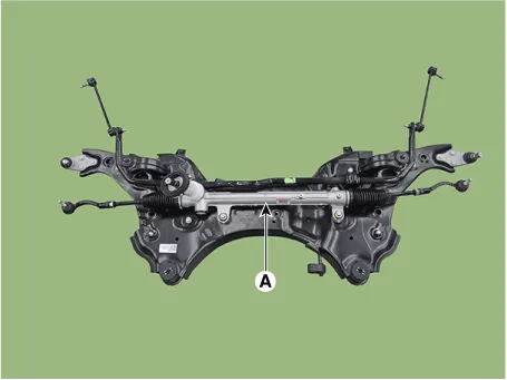
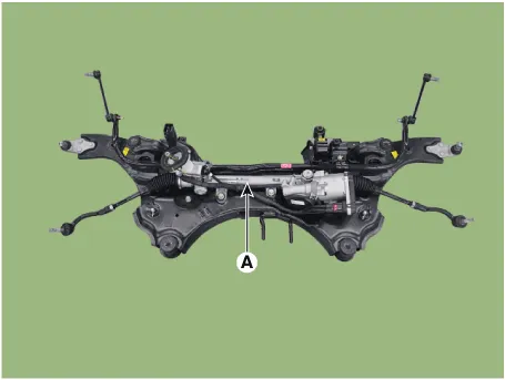
| 15. |
Remove the steering gearbox (A) from the front sub frame by loosening
the mounting bolts.
[C-MDPS]
[R-MDPS]
|
| 16. |
Loosen the mounting bolts and then remove the stabilizer bar (A).
|
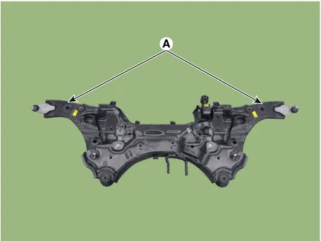
| 17. |
Remove the front lower arm (A) from the sub frame.
|
| Installation |
| 1. |
Install in the reverse order of removal.
|
| 2. |
Check the alignment.
(Refer to Suspension System - "Alingment")
|
Repair procedures Removal 1. Turn the ignition switch OFF and disconnect the battery negative (-) cable. 2.
Other information:
Hyundai Palisade (LX2) 2020-2026 Service Manual: Specifications
Specification Air Conditioner Item Specification Compressor Type 7VSX18 (External Variable Displacement Swash Plate) Oil type & Capacity PAG 180 ± 10cc (6.
Hyundai Palisade (LX2) 2020-2026 Service Manual: Repair procedures
Replacement 1. Disconnect the negative (-) battery terminal. 2. Remove the luggage side trim (Refer to Body - "Luggage Side Trim ") 3. Separate the rear mode actuator connector (A), loosen the mounting screws and remove the rear mode ac
Categories
- Manuals Home
- Hyundai Palisade Owners Manual
- Hyundai Palisade Service Manual
- Body Electrical System
- Body (Interior and Exterior)
- Lift and Support Points
- New on site
- Most important about car
