
Hyundai Palisade (LX2): Transfer Assembly / Front Wheel Transfer Assembly
Components and components location
| Components Location |
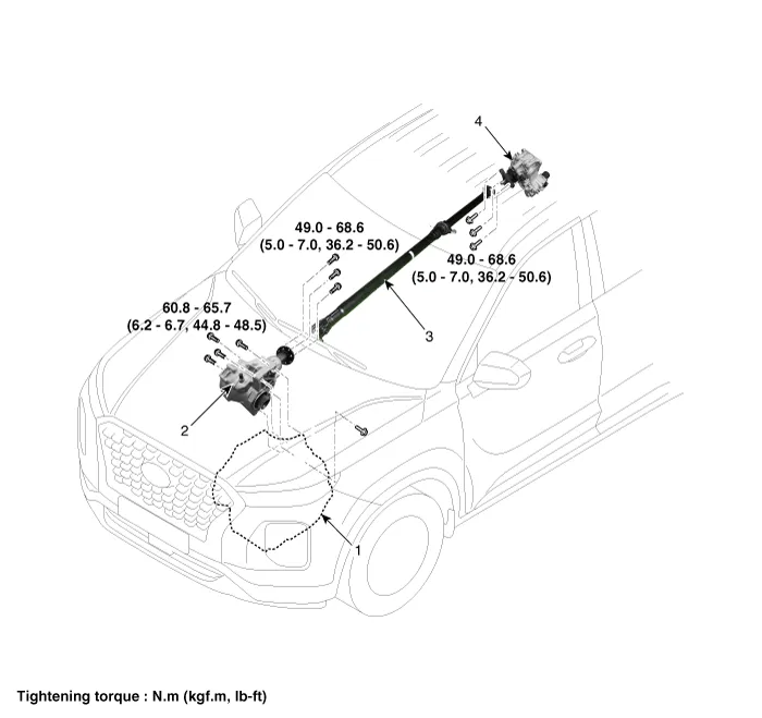
| 1. Trasaxle
assembly 2. Transfer assembly |
3. Propeller
shaft assembly 4. Coupling assembly |
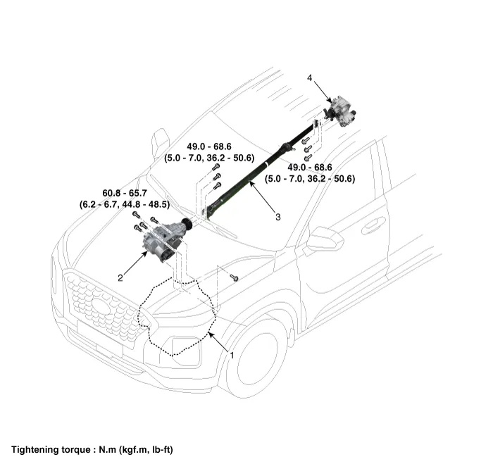
| 1. Trasaxle
assembly 2. Transfer assembly |
3. Propeller
shaft assembly 4. Coupling assembly |
Repair procedures
| Removal |
| 1. |
Remove the under cover.
(Refer to Engine Mechanical System - "Engine Room Under Cover")
|
| 2. |
Remove the sub frame.
(Refet to Suspension System - "Sub Frame")
|
| 3. |
Remove the front drive shaft assembly. [Right side]
(Refer to Driveshaft and Axle - "Front Driveshaft")
|
| 4. |
Remove the front muffler. [Gasoline 3.5/ 3.8]
(Refer to Engine Mechanical System - "Muffler")
|
| 5. |
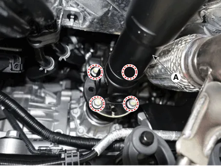
Remove the front propeller shaft assembly (A) from the transfer assembly.
[Diesel 2.2]
[Gasoline 3.5, 3.8]
|

| 6. |
Remove the transfer case assembly.
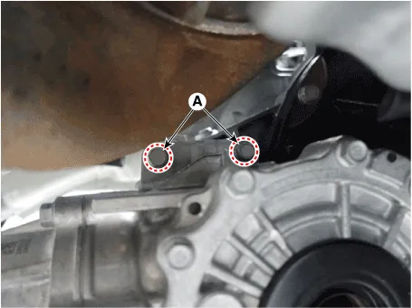
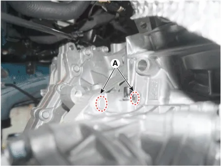
1) Loosen the transafer assembly upper mounting bolts (A).
[Diesel 2.2]
[Gasoline 3.5, 3.8]
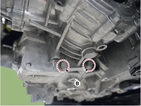
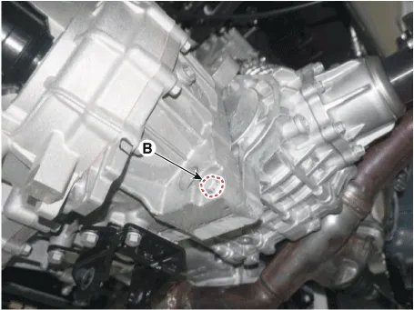
2-1) Loosen the transfer assembly lower mounting bolts (B). [Transfer
->Transaxle]
[Diesel 2.2]
[Gasoline 3.5, 3.8]
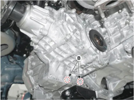
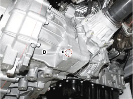
2-2) Loosen the transfer assembly lower mounting bolts (B). [Transaxle
->Transfer]
[Diesel 2.2]
[Gasoline 3.5, 3.8]
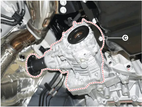
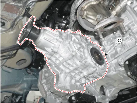
3) Remove the transfer assembly (C).
[Diesel 2.2]
[Gasoline 3.5, 3.8]
|
| Installation |
| 1. |
To install, reverse the removal procedures.
|


Repair procedures Inspection • Transfer oil should be inspected and refilled every 60,000 km (40,000 mile) / 4 year.
Repair procedures Replacement [Driveshaft side oil seal] 1. Remove the under cover. (Refer to Engine Mechanical System - "Engine Room Under Cover") 2.
Other information:
Hyundai Palisade (LX2) 2020-2026 Service Manual: Compressor
Description and operation Description The compressor is the power unit of the A/C system. It is located on the side of engine block and driven by a V-belt of the engine. The compressor changes low pressure and low temperature refrigerant gas into high pressure and high temperature refrigerant gas.
Hyundai Palisade (LX2) 2020-2026 Service Manual: Cruise Control (CC) Switch
Components and components location Components 1. Remote control switch (Audio swtich) 2. Remote control switch (Cruise control switch) Schematic diagrams Circuit Diagram Repair procedures Removal 1.
Categories
- Manuals Home
- Hyundai Palisade Owners Manual
- Hyundai Palisade Service Manual
- Components and components location
- Electrochromatic Mirror (ECM) with homelink system
- Lift and Support Points
- New on site
- Most important about car
