
Hyundai Palisade (LX2): Engine Mechanical System / Special service tools
Hyundai Palisade (LX2) 2020-2026 Service Manual / Engine Mechanical System / Special service tools
| Special Service Tools |
|
Tool (Number and name) |
Illustration |
Use |
|
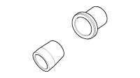
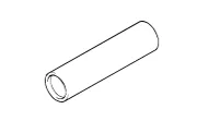
Crankshaft front oil seal installer (09231-3C100) |
|
Installation of the front oil seal |
|
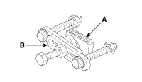
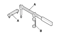
Ring gear stopper A : 09231-3N100 B : 09231-2B100 |
|
Removal and installation of crankshaft pulley bolt |
|
Ring gear stopper A : 09231-3D100 B : 09231-2W100 |
|
Removal and installation of crankshaft pulley bolt. |
|
Torque angle adapter (09221-4A000) |
|
Installation of bolts & nuts needing an angular method |
|
Valve stem seal remover (09222-29000) |
|
Removal of the valve stem seal |
|
Valve stem seal installer (09222-3C100) |
|
Installation of the valve stem seal |
|
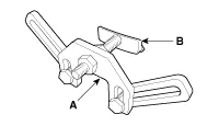
Valve spring compressor & holder A : 09222-3K000 B : 09222-3K100 |
|
Removal and installation of the intake or exhaust valves |
|
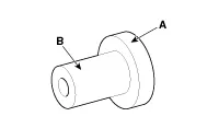
Crankshaft rear oil seal installer A : 09231-3C200 B : 09231-H1100 |
|
Installation of the crankshaft rear oil seal |
|
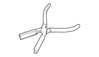
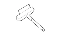
Oil pan remover (09215-3C000) |
|
Removal of oil pan |

Troubleshooting Symptom Suspect area Remedy Engine misfire with abnormal internal lower engine noises.
Other information:
Hyundai Palisade (LX2) 2020-2026 Service Manual: Repair procedures
Refrigerant System Service Basics (R-134a) Refrigerant Recovery Use only service equipment that is U.L-listed and is certified to meet the requirements of SAE J2210 to remove HFC-134a(R-134a) from the air conditioning system.
Hyundai Palisade (LX2) 2020-2026 Service Manual: Description and operation
Description • PDW consists of 8 sensors (front : 4 units, rear : 4 units) that are used to detect obstacles and transmit the result in three separate warning levels, the first, second and third to IBU via LIN communication.
Categories
- Manuals Home
- Hyundai Palisade Owners Manual
- Hyundai Palisade Service Manual
- Electrochromatic Mirror (ECM) with homelink system
- Repair procedures
- Body (Interior and Exterior)
- New on site
- Most important about car

Copyright © 2026 www.hpalisadelx.com - 0.0238