Hyundai Palisade (LX2): Motor Driven Power Steering / Schematic diagrams
Hyundai Palisade (LX2) 2020-2026 Service Manual / Steering System / Motor Driven Power Steering / Schematic diagrams
| Schematic Diagrams |
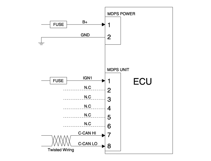
MDPS Circuit Diagram
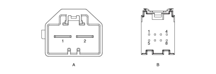
Harness Connector
|
Type |
Pin No |
Description |
|
MDPS Power |
1 |
Battery + |
|
2 |
Battery - |
|
|
MDPS Unit |
1 |
IGN1 |
|
2 |
- |
|
|
3 |
- |
|
|
4 |
- |
|
|
5 |
- |
|
|
6 |
- |
|
|
7 |
C-CAN [High] |
|
|
8 |
C-CAN [Low] |
Components [C-MDPS] 1. Steering wheel 2. Steering column 3. MDPS powerpack assembly 4. Universal joint 5.
A/S Repair produres [C-MDPS] MDPS System A/S Workflow ‚φ Noise / malfunction Inspection ‚Ď° Warning lamp (DTC) / CAN Line error 2 - 1 Checking Connectors and Wiring 1.
Other information:
Hyundai Palisade (LX2) 2020-2026 Service Manual: A/C Pressure Transducer
Description and operation Description The A/C Pressure Transducer (APT) converts the pressure value of high pressure line into voltage value after measuring it. By converted voltage value, engine ECU controls the cooling fan by operating it high speed or low speed.
Hyundai Palisade (LX2) 2020-2026 Service Manual: Components and components location
Categories
- Manuals Home
- Hyundai Palisade Owners Manual
- Hyundai Palisade Service Manual
- Electrochromatic Mirror (ECM) with homelink system
- Body Electrical System
- Automatic Transaxle Fluid (ATF)
- New on site
- Most important about car

Copyright © 2026 www.hpalisadelx.com - 0.0178