Hyundai Palisade (LX2): Auto Lighting Control System / Schematic diagrams
| Circuit Diagram |
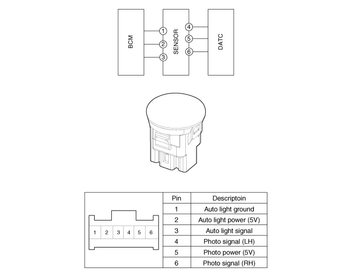
Component Location 1. Auto light sensor 2. Head lamps 3. Lighting switch (Auto) 4. Tail lamps 5. IBU (Integrated Body Control Unit)
Description It's a system that uses illumination sensor to automatically turn ON the tail lamp and head lamp based on the change in surrounding environment's illumination condition.
Other information:
Hyundai Palisade (LX2) 2020-2026 Service Manual: Rear Temperature Control Actuator
Repair procedures Replacement 1. Disconnect the negative (-) battery terminal. 2. Remove the luggage side trim (Refer to Body - "Luggage Side Trim ") 3. Separate the rear temperature actuator connector (A), loosen the mounting screws a
Hyundai Palisade (LX2) 2020-2026 Service Manual: Smart Cruise Control (SCC) Switch
Components and components location Components 1. Remote control switch (Audio swtich) 2. Remote control switch (Cruise control switch) Schematic diagrams Circuit Diagram Trip + SCC Repair procedures Removal 1.
Categories
- Manuals Home
- Hyundai Palisade Owners Manual
- Hyundai Palisade Service Manual
- Troubleshooting
- Rain Sensor
- Emergency liftgate safety release
- New on site
- Most important about car
