Hyundai Palisade (LX2): Rear Suspension System / Rear Lower Arm
Repair procedures
| Removal |
| 1. |
Loosen the wheel nuts slightly.
Raise the vehicle, and make sure it is securely supported.
|
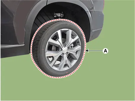
| 2. |
Remove the rear wheel and tire (A) from rear hub.
|

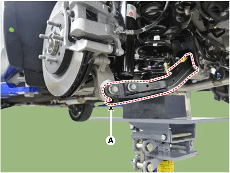
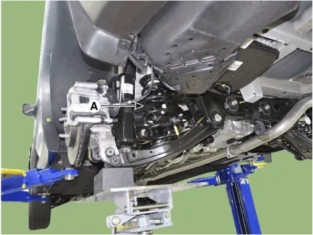
| 3. |
Loosen the bolt & nut and then remove the rear lower arm (A) from the
rear axle.
|

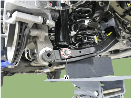
| 4. |
Loosen the bolt & nut (A) and then disconnect the rear shock absorber
from the lower arm.
|
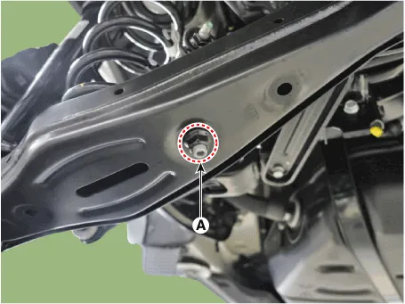
| 5. |
Loosen the nut (A) and then disconnect the stabilizer bar link from
the lower arm.
|
| 6. |
Remove the coil spring (A).
|
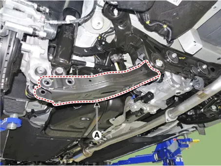
| 7. |
Loosen the bolt & nut and then remove the rear lower arm (A).
|
| Inspection |
| 1. |
Check the bushing for wear and deterioration.
|
| 2. |
Check the rear lower arm for deformation.
|
| 3. |
Check the coil spring and spring pad for deterioration and deformation.
|
| 4. |
Check for all bolts and nut.
|
| Installation |
| 1. |
Install in the reverse order of removal.
|
| 2. |
Check the alignment.
(Refer to Suspension System - "Alingment")
|
Repair procedures Removal 1. Loosen the wheel nuts slightly. Raise the vehicle, and make sure it is securely supported.
Repair procedures Removal 1. Loosen the wheel nuts slightly. Raise the vehicle, and make sure it is securely supported.
Other information:
Hyundai Palisade (LX2) 2020-2026 Service Manual: Smart Cruise Control (SCC) Switch
Components and components location Components 1. Remote control switch (Audio swtich) 2. Remote control switch (Cruise control switch) Schematic diagrams Circuit Diagram Trip + SCC Repair procedures Removal 1.
Hyundai Palisade (LX2) 2020-2026 Service Manual: Repair procedures
Inspection Tolerance Compensation Tolerance compensation compensates for the error margins of around view video that occur due to the installation tolerance when the four cameras that comprise the SVM system are installed. You must carry out tolerance compensation if you do any of the following.
Categories
- Manuals Home
- Hyundai Palisade Owners Manual
- Hyundai Palisade Service Manual
- Engine Mechanical System
- How to reset the power liftgate
- Rain Sensor
- New on site
- Most important about car
