Hyundai Palisade (LX2): Rear Glass Defogger / Rear Glass Defogger Printed Heater
Repair procedures
| Inspection |
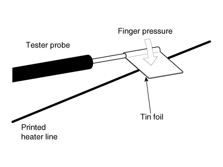
Wrap tin foil around the end of the voltmeter test lead to prevent damaging
the heater line. Apply finger pressure on the tin foil, moving the tin
foil along the grid line to check for open circuits.
|

| 1. |
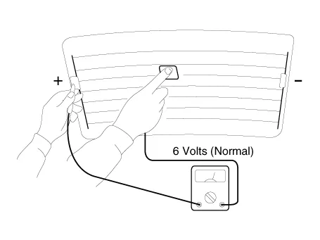
Turn on the defogger switch and use a voltmeter to measure the voltage
of each heater line at the glass center point. If a voltage of approximately
6V is indicated by the voltmeter, the heater line of the rear window
is considered satisfactory.
|
| 2. |
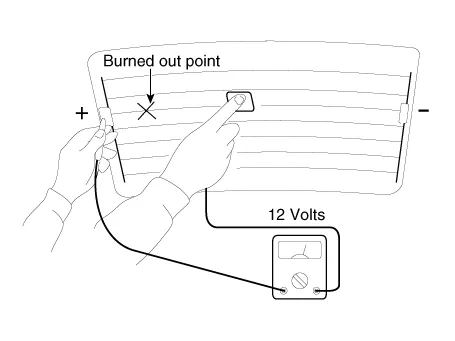
If a heater line is burned out between the center point and (+) terminal,
the voltmeter will indicate 12V.
|
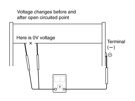
| 3. |
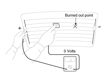
If a heater line is burned out between the center point and (-) terminal,
the voltmeter will indicate 0V.
|
| 4. |
To check for open circuits, slowly move the test lead in the direction
that the open circuit seems to exist. Try to find a point where a voltage
is generated or changes to 0V. The point where the voltage has changed
is the open-circuit point.
|
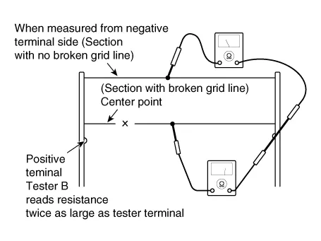
| 5. |
Use an ohmmeter to measure the resistance of each heater line between
a terminal and the center of a grid line, and between the same terminal
and the center of one adjacent heater line. The section with a broken
heater line will have a resistance twice that in other sections. In
the affected section, move the test lead to a position where the resistance
sharply changes.
|
| 1. |
Conductive paint.
|
| 2. |
Paint thinner.
|
| 3. |
Masking tape.
|
| 4. |
Silicone remover.
|
| 5. |
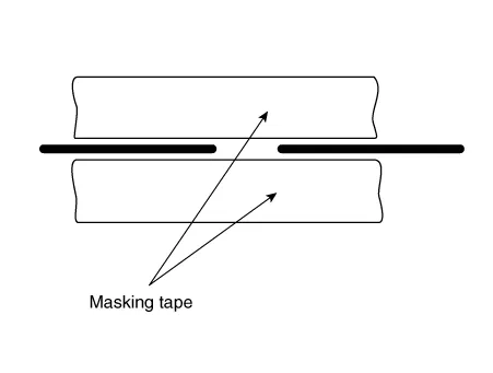
Using a thin brush :
Wipe the glass adjacent to the broken heater line, clean with silicone
remover and attach the masking tape as shown. Shake the conductive paint
container well, and apply three coats with a brush at intervals of about
15 minutes apart. Remove the tape and allow sufficient time for drying
before applying power. For a better finish, scrape away excess deposits
with a knife after the paint has completely dried. (Allow 24 hours).
|
Component Location 1. Rear glass defogger relay (Buil-in engine room relay box) 2. Rear glass defogger switch (Dual type) 3.
Repair procedures Diagnosis with Diagnostic tool Diagnosis with Diagnostic tool 1. In the body electrical system, failure can be quickly diagnosed by using the vehicle diagnostic system (Diagnostic tool).
Other information:
Hyundai Palisade (LX2) 2020-2026 Service Manual: Photo Sensor
Description and operation Description The photo sensor is located at the center of the defrost nozzles. The photo sensor contains a photovoltaic (sensitive to sunlight) diode. The solar radiation received by its light receiving portion, generates an electromotive force in proportion to the amount of radiation received wh
Hyundai Palisade (LX2) 2020-2026 Service Manual: Power Mosfet (DATC)
Repair procedures Inspection 1. Turn the ignition switch ON. 2. Manually operate the control switch and measure the voltage of the blower motor. 3. Select the control switch to raise the voltage until high speed.
Categories
- Manuals Home
- Hyundai Palisade Owners Manual
- Hyundai Palisade Service Manual
- Electronic Child Safety Lock System
- Resetting the Driver's Seat Memory System
- Automatic Transaxle System (A8LF1)
- New on site
- Most important about car
