Hyundai Palisade (LX2): Crankcase Emission Control System / Positive Crankcase Ventilation (PCV) Valve
Hyundai Palisade (LX2) 2020-2026 Service Manual / Emission Control System / Crankcase Emission Control System / Positive Crankcase Ventilation (PCV) Valve
Description and operation
| Operation Principle |

Repair procedures
| Removal |
| 1. |
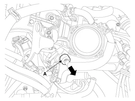
Release the PCV pad.
|
| 2. |
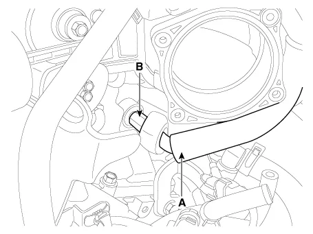
Disconnect the vapor hose (A).
|
| 3. |
Remove the PCV valve (B).
|
| Inspection |
| 1. |
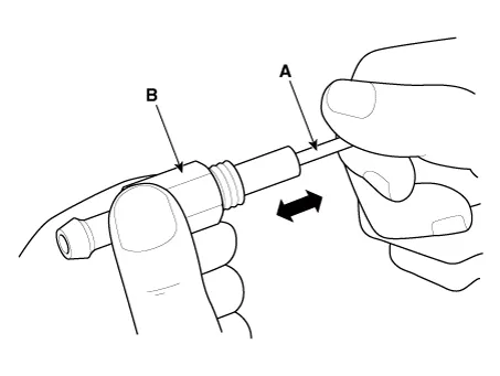
Insert a thin stick (A) into the PCV valve (B) from the threaded side
to check for plunger movement.
|

| Installation |
| 1. |
Install in the reverse order of removal.
|

Inspection 1. After disconnecting the vapor hose from the PCV valve, remove the PCV valve. 2. Reconnect the PCV valve to the vapor hose.
Other information:
Hyundai Palisade (LX2) 2020-2026 Service Manual: Wireless Charging Lamp
Components and positions Components Repair procedures Removal Handling wireless charging system parts by wet hands may cause electric shock.
Hyundai Palisade (LX2) 2020-2026 Service Manual: General safety information and caution
Instructions (R-134a) When Handling Refrigerant 1. R-134a liquid refrigerant is highly volatile. A drop on the skin of your hand could result in localized frostbite. When handling the refrigerant, be sure to wear gloves.
Categories
- Manuals Home
- Hyundai Palisade Owners Manual
- Hyundai Palisade Service Manual
- General Tightening Torque Table
- Maintenance
- Electronic Child Safety Lock System
- New on site
- Most important about car

Copyright © 2026 www.hpalisadelx.com - 0.0146