Hyundai Palisade (LX2): Engine Control System / Oil Pressure Sensor (OPS)
Description and operation
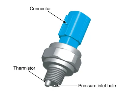
| Description |
Specifications
| Specifications |
|
Pressure (Bar) |
Output Voltage (V) [Vref=5V] |
|
0 |
0.46 - 0.54 |
|
2 |
1.25 - 1.35 |
|
4 |
2.05 - 2.15 |
|
6 |
2.84 - 2.96 |
|
10 |
4.42 - 4.58 |
Schematic diagrams
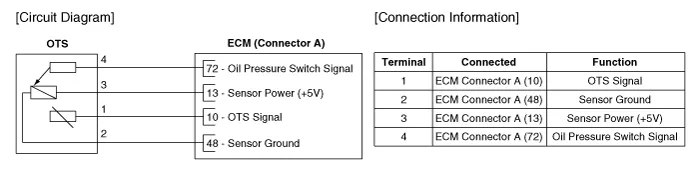
| Circuit Diagram |
Repair procedures
| Inspection |
| 1. |
Switch "OFF" the ignition.
|
| 2. |
Disconnect the OPS connector.
|
| 3. |
Remove the OPS.
|
| 4. |
After immersing the thermistor of the sensor into engine coolant, measure
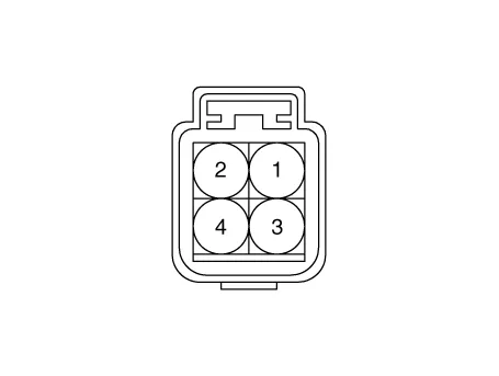
resistance between the OPS terminals 2 and 4.
|
| 5. |
Check that the resistance is within the specification.
|
| Removal |
| 1. |
Refer to Engine Mechanical System - "Oil Pressure Sensor"
|
| Installation |
| 1. |
Refer to Engine Mechanical System - "Oil Pressure Sensor"
|
Description and operation Description Continuous Variable Valve Timing (CVVT) system advances or retards the valve timing of the intake and exhaust valve in accordance with the ECM control signal which is calculated by the engine speed and load.
Description and operation Description Installed on the accelerator pedal module, the Accelerator Position Sensor (APS) detects the rotation angle of the accelerator pedal.
Other information:
Hyundai Palisade (LX2) 2020-2026 Service Manual: Description and operation
Description Blind-Spot Radar is a system that measures the relative speed and distance from the following vehicles by using two electromagnetic wave radar sensors attached to the rear bumper, and detects any vehicle within the blind spot zone and gives off alarm (visual and auditory).
Hyundai Palisade (LX2) 2020-2026 Service Manual: Troubleshooting
Troubleshooting 1) After replacing H/UNIT, always check that the system operates properly. 2) If the failure persists after replacing the H/UNIT, do not replace the unit.
Categories
- Manuals Home
- Hyundai Palisade Owners Manual
- Hyundai Palisade Service Manual
- Engine Mechanical System
- Emergency liftgate safety release
- Removing and Storing the Spare Tire
- New on site
- Most important about car
