Hyundai Palisade (LX2): Intake And Exhaust System / Intake Manifold
Hyundai Palisade (LX2) 2020-2026 Service Manual / Engine Mechanical System / Intake And Exhaust System / Intake Manifold
Components and components location
| Components |
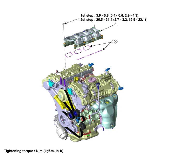
| 1. Intake manifold |
2. Intake manifold gasket |
Repair procedures
| Removal and Installation |
| 1. |
Remove the engine cover.
(Refer to Engine and Transaxle Assembly - "Engine Cover")
|
| 2. |
Remove the air cleaner assembly.
(Refer to Intake And Exhaust System - "Air Cleaner")
|
| 3. |
Remove the surge tank.
(Refer to Intake And Exhaust System - "Surge Tank")
|
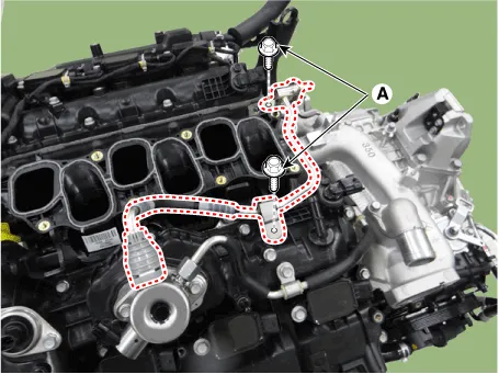
| 4. |
Remove the low pressure fuel line mounting bolts (A).
|
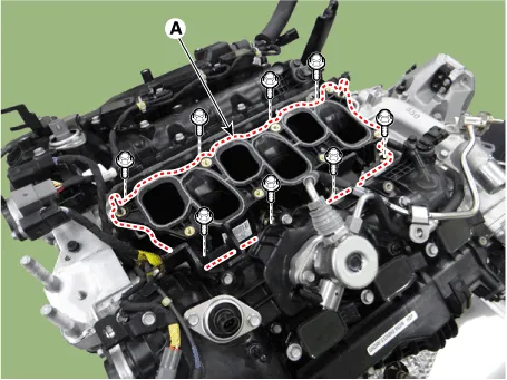
| 5. |
Remove the intake manifold (A).
|

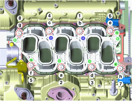
| 6. |
Install in the reverse order of removal.
|

Repair procedures Removal and Installation VIS 1 [Intake Manifold] 1. Disconnect the battery negative terminal. 2.
Components and components location Components 1. LH Exhaust manifold gasket 2. LH Exhaust manifold 3. LH Heat protector 4.
Other information:
Hyundai Palisade (LX2) 2020-2026 Service Manual: In-car Sensor
Description and operation Description The In-car air temperature sensor is built in the heater & A/C control unit. The sensor consists of a thermistor that measures the inside temperature. The signal decided by the resistance value that changes in accordance with perceived inside temperature, is delivered to heater co
Hyundai Palisade (LX2) 2020-2026 Service Manual: Components and components location
Categories
- Manuals Home
- Hyundai Palisade Owners Manual
- Hyundai Palisade Service Manual
- Electrochromatic Mirror (ECM) with homelink system
- Engine Mechanical System
- Rain Sensor
- New on site
- Most important about car

Copyright © 2026 www.hpalisadelx.com - 0.024