Hyundai Palisade (LX2): Audio / USB jack
Schematic diagrams
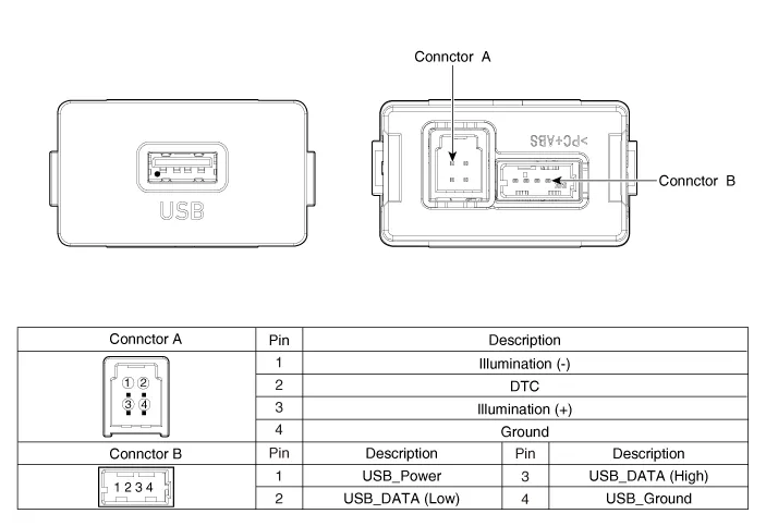
| Circuit Diagram |
Description and operation
| Description |
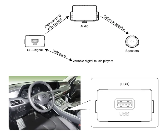
The AUX, iPod and USB JACK on the center console is for customers who like to
listen to external portable music players like the MP3, iPod, earphone, USB
memory stick, CD player and etc., through the vehicle's sound system when it
is linked to this jack.
If sound distortion occurs it may be due to a mismatch of specifications between
units.
Repair procedures
| Removal |
| 1. |
Disconnect the negative (-) battery terminal.
|
| 2. |
Remove the front console assembly.
(Refer to Body - Floor Console Assembly")
|
| 3. |
Remove the front console garnish (A).
|


| 4. |
Remove the front console tray assembly (A).
|

| 5. |
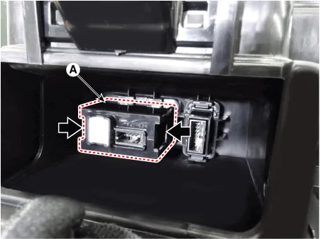
Disconnect the connector (A).
|

| 6. |
Remove the USB (A) by pushing the fixed clip in the direction of the
arrow as lillustration below.
|
| Installation |
| 1. |
Install the USB.
|
| 2. |
Install the front console assembly.
|
| 3. |
Connect the negative (-) battery connector.
|
Components and components location Components Repair procedures Removal 1. Disconnct the negative (-) battery terminal.
Other information:
Hyundai Palisade (LX2) 2020-2026 Service Manual: Immobilizer Control Unit
Repair procedures Removal 1. Disconnect the negative (-) battery terminal. 2. Remove the glove box housing. (Refer to Body - "Glove Box Housing Cover") 3.
Hyundai Palisade (LX2) 2020-2026 Service Manual: Description and operation
Description Blind-Spot Radar is a system that measures the relative speed and distance from the following vehicles by using two electromagnetic wave radar sensors attached to the rear bumper, and detects any vehicle within the blind spot zone and gives off alarm (visual and auditory).
Categories
- Manuals Home
- Hyundai Palisade Owners Manual
- Hyundai Palisade Service Manual
- Scheduled maintenance services
- Rain Sensor
- How to reset the power liftgate
- New on site
- Most important about car

Copyright © 2026 www.hpalisadelx.com - 0.0118