Hyundai Palisade (LX2): Starting System / Starter Relay
Hyundai Palisade (LX2) 2020-2026 Service Manual / Engine Electrical System / Starting System / Starter Relay
Repair procedures
| Inspection |
| 1. |
Turn ignition switch OFF and disconnect the negative (-) battery terminal.
|
| 2. |
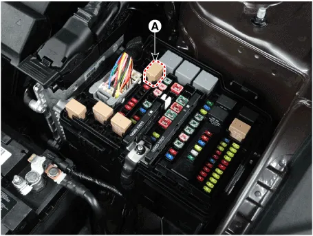
Remove the fuse box cover.
|
| 3. |
Remove the starter relay (A).
|
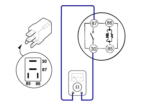
| 4. |
Check for continuity between the terminals (30 and 87) using an ohmmeter.
|
| 5. |
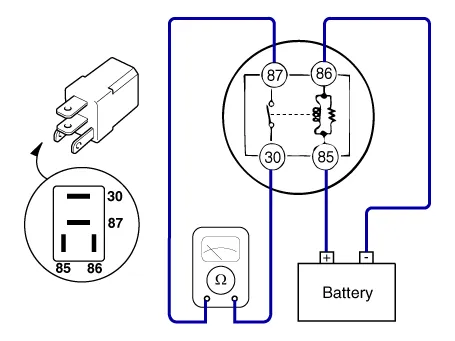
Apply 12V to the terminal 85 and ground to the terminal 86 and then
check for continuity between the terminals (30 and 87).
|
| 6. |
Install the starter relay.
|
| 7. |
Install the fuse box cover.
|
Specifications Specification Starter Item Specification Rated voltage 12 V, 1.
Other information:
Hyundai Palisade (LX2) 2020-2026 Service Manual: General safety information and caution
Instructions (R-134a) When Handling Refrigerant 1. R-134a liquid refrigerant is highly volatile. A drop on the skin of your hand could result in localized frostbite. When handling the refrigerant, be sure to wear gloves.
Hyundai Palisade (LX2) 2020-2026 Service Manual: Schematic diagrams
Trouble Symptom Charts Component Parts and Function Outline Component part Function Cruise Control Switch Input the set speed and distance to the SCC ECU. Instrument Cluster Display various information inputted from SCC.
Categories
- Manuals Home
- Hyundai Palisade Owners Manual
- Hyundai Palisade Service Manual
- Rear Heater Unit
- Automatic Transaxle Fluid (ATF)
- Body (Interior and Exterior)
- New on site
- Most important about car

Copyright © 2026 www.hpalisadelx.com - 0.0167