
Hyundai Palisade (LX2): Evaporative Emission Control System / Schematic diagrams
| Schematic Diagram |
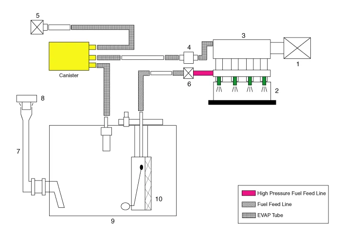
| 1. Air cleaner 2. Delivery pipe & injector 3. Engine 4. Purge control solenoid valve (PCSV) 5. Fuel tank air filter |
6. High pressure fuel pump 7. Fuel filler hose 8. Fuel filler cap 9. Fuel tank 10. Low pressure fuel pump |
Description Evaporative Emission Control System prevents fuel vapor stored in fuel tank from vaporizing into the atmosphere. When the fuel evaporates from the fuel tank, the vapor passes through vent hoses or tubes into canister filled with charcoal and the canister temporarily holds the vapor in the charcoal.
Repair procedures Removal 1. Switch "OFF" the ignition and disconnect the negative (-) battery terminal. 2.
Other information:
Hyundai Palisade (LX2) 2020-2026 Service Manual: Heater & A/C Control Unit (DATC)
Components and components location Component Connector Pin Function Connector PIN No Pin Function Connector PIN No Pin Function A 1 Battery A 21 IGN2 2
Hyundai Palisade (LX2) 2020-2026 Service Manual: Description and operation
Description Blind-Spot Radar is a system that measures the relative speed and distance from the following vehicles by using two electromagnetic wave radar sensors attached to the rear bumper, and detects any vehicle within the blind spot zone and gives off alarm (visual and auditory).
Categories
- Manuals Home
- Hyundai Palisade Owners Manual
- Hyundai Palisade Service Manual
- Rain Sensor
- Engine Control/Fuel System
- Repair procedures
- New on site
- Most important about car
