Hyundai Palisade (LX2): Evaporative Emission Control System / Canister
Repair procedures
| Removal |
| 1. |
Switch "OFF" the ignition and disconnect the negative (-) battery terminal.
|
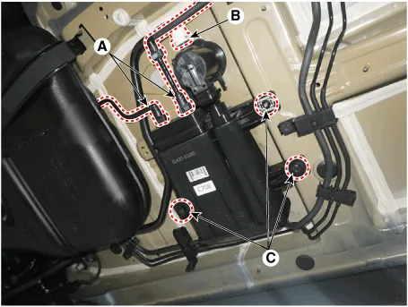
| 2. |
Disconnect the vent hose quick-connector (B), the vapor hose quick-connector
(A) from the canister.
|
| 3. |
Remove the fuel tank air filter assembly after removing the mounting
bolts (C).
|
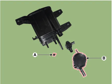
| 4. |
Remove the fuel tank air filter mounting bolt (A).
|
| 5. |
Remove the clip, and then separate the fuel tank air filter (B) from
the canister after rotating it in the direction of the arrow in the
figure.
|
| Inspection |
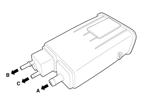
| 1. |
Check for the following items visually.
A : Canister ↔ Atmosphere
B : Canister ↔ Fuel Tank (Fuel Pump)
C : Canister ↔ Intake Manifold
|
| Installation |
| 1. |
Install in the reverse order of removal.
|
Schematic Diagram 1. Air cleaner 2. Delivery pipe & injector 3. Engine 4. Purge control solenoid valve (PCSV) 5.
Specifications Specification Item Specification Coil Resistance (Ω) 18.5 - 22.
Other information:
Hyundai Palisade (LX2) 2020-2026 Service Manual: Heater Unit
Components and components location Component Location 1. Heater unit assembly Components 1. Heater core assembly 2. Heater unit pad 3. Heater lower cover 4. Drain hose 5.
Hyundai Palisade (LX2) 2020-2026 Service Manual: Smart Cruise Control (SCC) Switch
Components and components location Components 1. Remote control switch (Audio swtich) 2. Remote control switch (Cruise control switch) Schematic diagrams Circuit Diagram Trip + SCC Repair procedures Removal 1.
Categories
- Manuals Home
- Hyundai Palisade Owners Manual
- Hyundai Palisade Service Manual
- Emergency liftgate safety release
- How to reset the power liftgate
- Electrochromatic Mirror (ECM) with homelink system
- New on site
- Most important about car
