Hyundai Palisade (LX2): Parking Brake System / Repair procedures
| Removal |
|

| 1. |
Turn ignition switch off and disconnect the battery (-) cable from the
battery.
|
| 2. |
Remove the crash pad lower pannel.
(Refer to Body - " Crash Pad Lower Pannel")
|
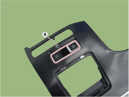
| 3. |
Loosen the guide screw and then removing the EPB switch (A).
|
| 1. |
Turn ignition switch off and disconnect the battery (-) cable from the
battery.
|
| 2. |
Remove the rear wheel and tire.
|
| 3. |
Remove the EPB actuator from rear caliper.
(Refer to Brake System - "Rear Disc Brake")
|
Circuit Diagram Terminal Function Pin No Fuction Pin No Fuction 6 Electrical parking brake signal 1 2 Rear right EPB motor power 7 Electrical parking brake signal 2 3 Rear right EPB motor ground 8 Electrical parking brake signal 3 12 Rear left EPB motor ground 9 Electrical parking brake signal 4 13 Rear left EPB motor power
Other information:
Hyundai Palisade (LX2) 2020-2026 Service Manual: Heater & A/C Control Unit (Rear)
Components and components location Component Connector Pin Function Connector PIN No Pin Function Connector PIN No Pin Function A 1 Battery A 17 IGN2 2
Hyundai Palisade (LX2) 2020-2026 Service Manual: Description and operation
Description The smart cruise control system allows a driver to program the vehicle to control the speed and following distance by detecting the vehicle ahead without depressing the brake pedal or the accelerator pedal. 1.
Categories
- Manuals Home
- Hyundai Palisade Owners Manual
- Hyundai Palisade Service Manual
- Power Outlet
- Automatic Transaxle System (A8LF1)
- Convenient Features of Your Vehicle
- New on site
- Most important about car
