
Hyundai Palisade (LX2): Power Tailgate Module / Power Tailgate Unit
Hyundai Palisade (LX2) 2020-2026 Service Manual / Body Electrical System / Power Tailgate Module / Power Tailgate Unit
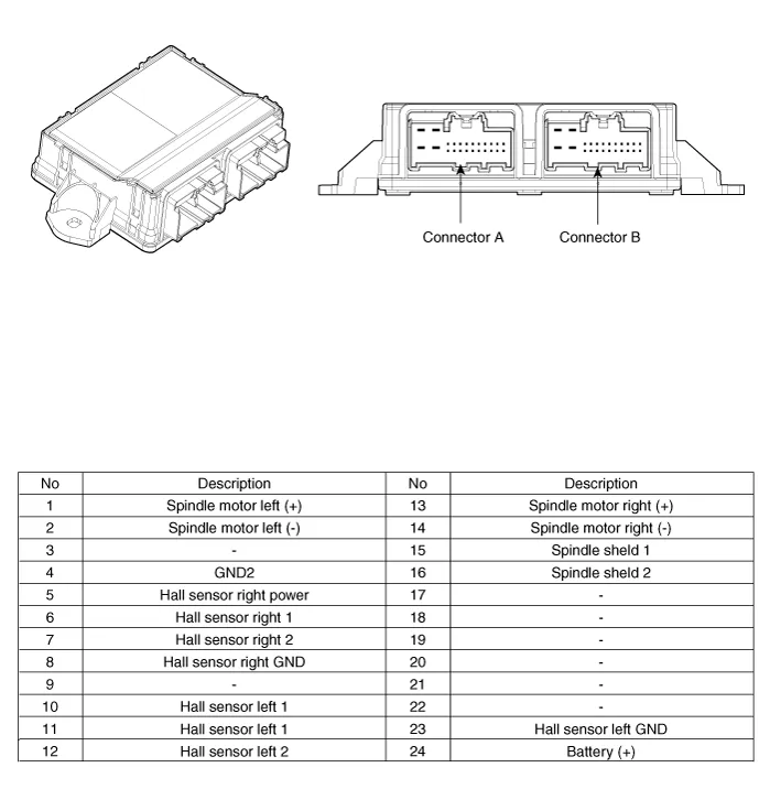
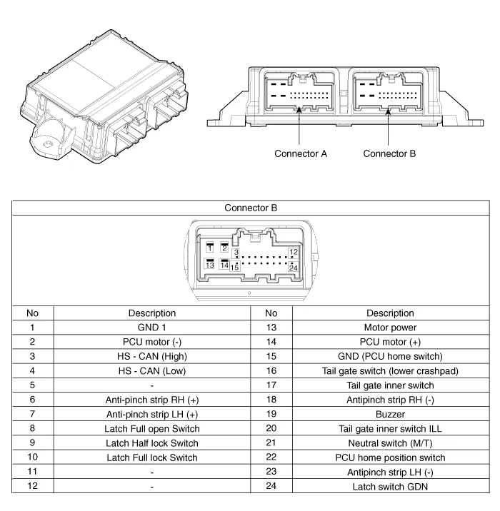
Components and components location
| Components |
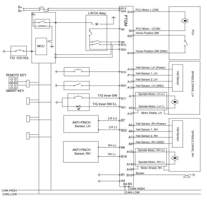
Schematic diagrams
| Circuit Diagram |
Repair procedures
| Removal |
|

| 1. |
Disconnect the negative (-) battery terminal.
|
| 2. |
Remove the rear left luggage side trim.
(Refer to Body - "Luggage Side Trim")
|
| 3. |
Remove the power tailgate unit connectors (A).
|
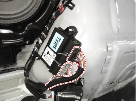
| 4. |
Remove the power tailgate unit (A).
|

| Installation |
| 1. |
Install the power tailgate unit.
|
| 2. |
Install the rear left luggage side trim.
|
| 3. |
Connect the negative (-) battery terminal.
|
| Inspection |
| Inspection of the Power Tailgate System |
Refer to Power Tailgate System - "Troubleshooting"
Failure Inspection Diagnosis with Diagnostic tool 1. In the body electrical system, failure can be quickly diagnosed by using the vehicle diagnostic system (Diagnostic tool).
Repair procedures Removal 1. Disconnect the negative (-) battery terminal. 2. Remove the tailgate trim.
Other information:
Hyundai Palisade (LX2) 2020-2026 Service Manual: Specification
Hyundai Palisade (LX2) 2020-2026 Service Manual: Rear Corner Safety ON/OFF Switch
Components and components location Circuit Diagram Repair procedures Inspection 1. Disconnect the negative (-) battery terminal. 2. Remove the crash pad lower panel. (Refer to Body - "Crashpad Lower Panel") 3.
Categories
- Manuals Home
- Hyundai Palisade Owners Manual
- Hyundai Palisade Service Manual
- Engine Control/Fuel System
- Emergency liftgate safety release
- Engine Mechanical System
- New on site
- Most important about car

Copyright В© 2026 www.hpalisadelx.com - 0.0185