Hyundai Palisade (LX2): Power Door Locks / Power Door Lock Actuators
Hyundai Palisade (LX2) 2020-2026 Service Manual / Body Electrical System / Power Door Locks / Power Door Lock Actuators
Repair procedures
| Inspection |
Front Door Lock Module Inspection
| 1. |
Remove the front door trim.
(Refer to Body - "Front Door Trim")
|
| 2. |
Remove the front door module.
(Refer to Body - "Front Door Module")
|
| 3. |
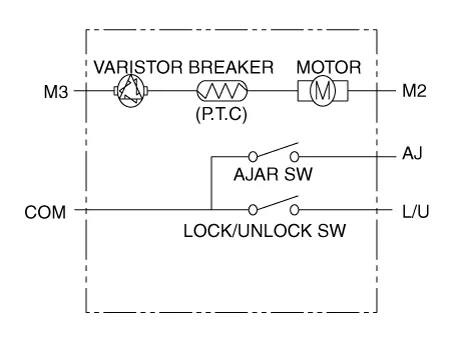
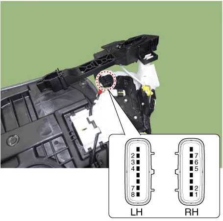
Disconnect the connectors from the actuator.
|
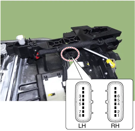
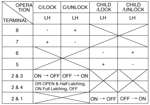
| 4. |
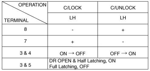
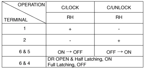
Check actuator operation by connecting power and ground according to
the table. To prevent damage to the actuator, apply battery voltage
only momentarily.
|
|||||||||||||||||||||||||||||||||||||||||||||||||
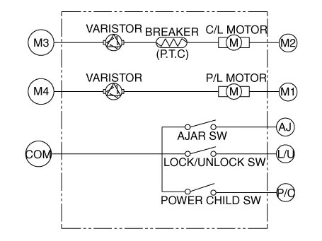
Rear Door Lock Module Inspection
| 1. |
Remove the rear door trim.
(Refer to Body - "Rear Door Trim")
|
| 2. |
Remove the rear door module.
(Refer to Body - "Rear Door Module")
|
| 3. |
Disconnect the connectors from the actuator.
|
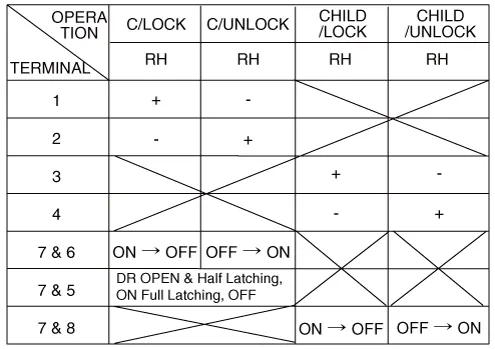
| 4. |
Check actuator operation by connecting power and ground according to
the table. To prevent damage to the actuator, apply battery voltage
only momentarily.
[Central Lock]
[Power Child Lock]
[Central Lock]
[Power Child Lock]
|
|||||||||||||||||||||||||||||
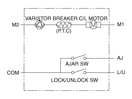

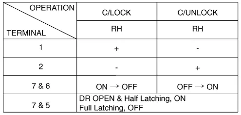
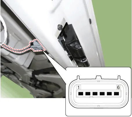
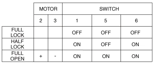
Tailgate Lock Module Inspection
| 1. |
Remove the tailgate trim.
(Refer to Body - "Tailgate Trim")
|
| 2. |
Disconnect the 4P connector from the actuator.
|
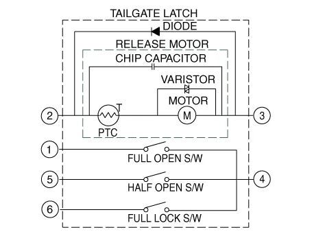
| 3. |
Check for continuity between the terminals in each switch position according
to the table.
|
Component Location 1. Driver power window main switch 2. IBU (Integrated Body Control Unit) 3. Door lock switch 4.
Repair procedures Diagnosis with Diagnostic tool Diagnosis with Diagnostic tool 1. In the body electrical system, failure can be quickly diagnosed by using the vehicle diagnostic system (Diagnostic tool).
Other information:
Hyundai Palisade (LX2) 2020-2026 Service Manual: Compressor
Description and operation Description The compressor is the power unit of the A/C system. It is located on the side of engine block and driven by a V-belt of the engine. The compressor changes low pressure and low temperature refrigerant gas into high pressure and high temperature refrigerant gas.
Hyundai Palisade (LX2) 2020-2026 Service Manual: Components and components location
Categories
- Manuals Home
- Hyundai Palisade Owners Manual
- Hyundai Palisade Service Manual
- Electrochromatic Mirror (ECM) with homelink system
- Body Electrical System
- Components and components location
- New on site
- Most important about car

Copyright © 2026 www.hpalisadelx.com - 0.0156