Hyundai Palisade (LX2): Mirror / Outside Rear View Mirror
Components and components location
| Component Location |
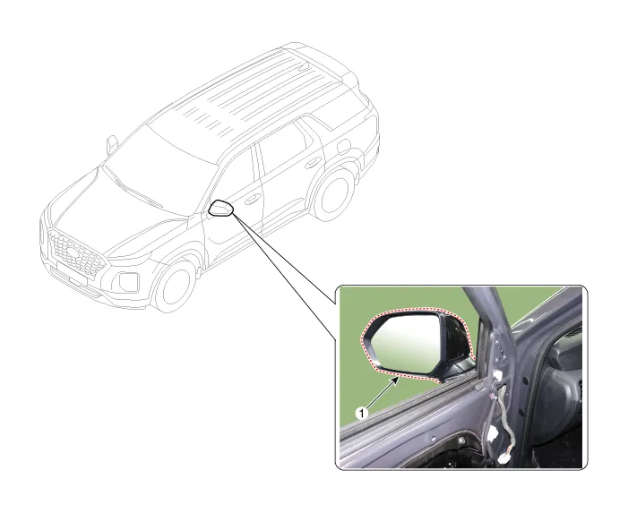
| 1. Outside rear view mirror
|
Repair procedures
| Replacement |
|

| 1. |
Remove the Front door trim.
(Refer to Front door - "Front Door Trim")
|
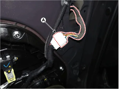
| 2. |
Press the lock pin and separate the outside mirror main connector (A).
|
| 3. |
Loosen the mounting bolts ,screws and remove the outside rear view mirror
(A).
|
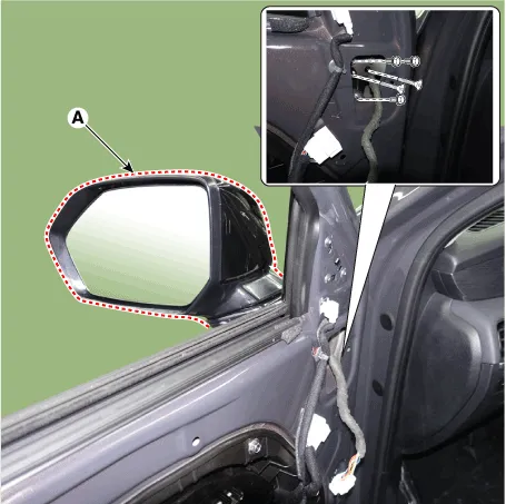
| 4. |
To install, reverse removal procedure.
|

| 1. |
Remove the outside rear view mirror.
(Refer to Mirror - "Outside Rear View Mirror")
|
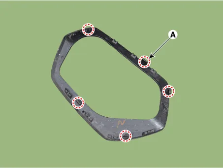
| 2. |
Remove the outside rear view mirror base pad (A).
|
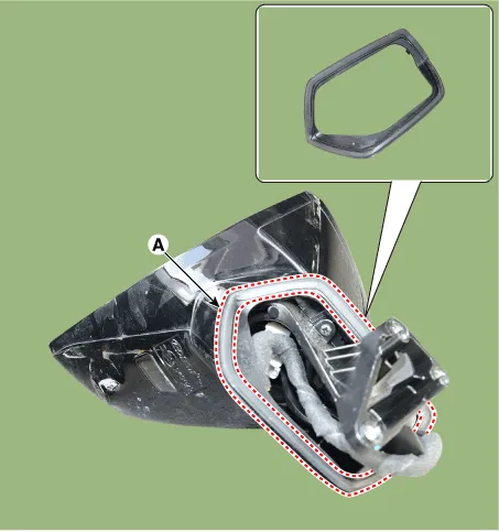

| 3. |
To install, reverse removal procedure.
|
Components and components location Component Location 1. Inside rear view mirror Repair procedures Replacement • When removing with a flat-tip screwdriver or remover, wrap protective tape around the tools to prevent damage to components.
Other information:
Hyundai Palisade (LX2) 2020-2026 Service Manual: Components and components location
Component Location 1. Start Stop Button(SSB) 2. FOB key 3. Tailgate open switch 4. Interior antenna 1 5. Interior antenna 2 6. Intergrated Body Control Unit (IBU) 7. Trunk antenna 8. Door handle & door antenna 9.
Hyundai Palisade (LX2) 2020-2026 Service Manual: Wireless Charging Lamp
Components and positions Components Repair procedures Removal Handling wireless charging system parts by wet hands may cause electric shock.
Categories
- Manuals Home
- Hyundai Palisade Owners Manual
- Hyundai Palisade Service Manual
- How to reset the power liftgate
- Rear Heater Unit
- Removing and Storing the Spare Tire
- New on site
- Most important about car
