
Hyundai Palisade (LX2): Transfer Assembly / Front Wheel Transfer Assembly
Components and components location
| Components Location |
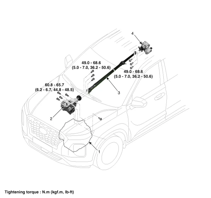
| 1. Trasaxle
assembly 2. Transfer assembly |
3. Propeller
shaft assembly 4. Coupling assembly |
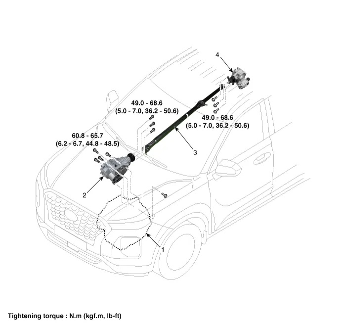
| 1. Trasaxle
assembly 2. Transfer assembly |
3. Propeller
shaft assembly 4. Coupling assembly |
Repair procedures
| Removal |
| 1. |
Remove the under cover.
(Refer to Engine Mechanical System - "Engine Room Under Cover")
|
| 2. |
Remove the sub frame.
(Refet to Suspension System - "Sub Frame")
|
| 3. |
Remove the front drive shaft assembly. [Right side]
(Refer to Driveshaft and Axle - "Front Driveshaft")
|
| 4. |
Remove the front muffler. [Gasoline 3.5/ 3.8]
(Refer to Engine Mechanical System - "Muffler")
|
| 5. |
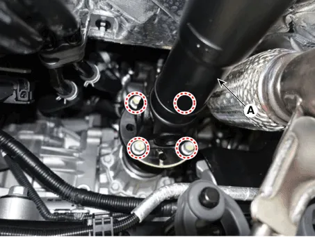
Remove the front propeller shaft assembly (A) from the transfer assembly.
[Diesel 2.2]
[Gasoline 3.5, 3.8]
|

| 6. |
Remove the transfer case assembly.
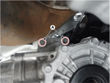
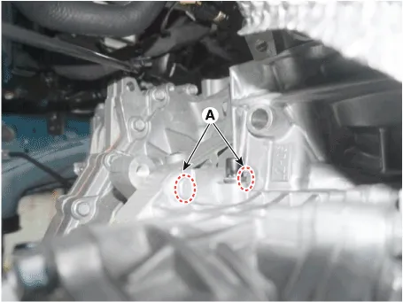
1) Loosen the transafer assembly upper mounting bolts (A).
[Diesel 2.2]
[Gasoline 3.5, 3.8]
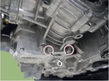
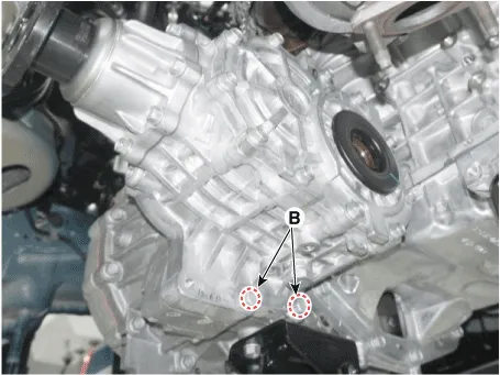
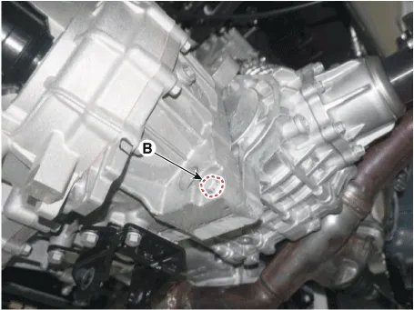
2-1) Loosen the transfer assembly lower mounting bolts (B). [Transfer
->Transaxle]
[Diesel 2.2]
[Gasoline 3.5, 3.8]
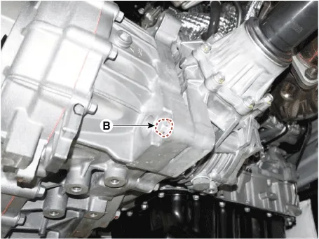
2-2) Loosen the transfer assembly lower mounting bolts (B). [Transaxle
->Transfer]
[Diesel 2.2]
[Gasoline 3.5, 3.8]
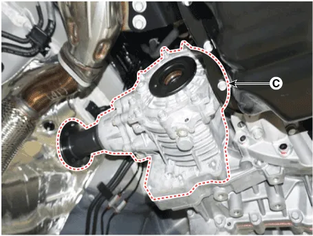
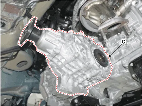
3) Remove the transfer assembly (C).
[Diesel 2.2]
[Gasoline 3.5, 3.8]
|
| Installation |
| 1. |
To install, reverse the removal procedures.
|

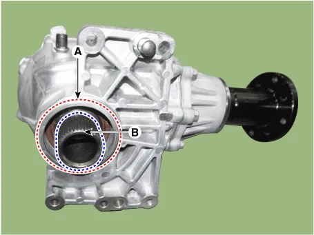

Repair procedures Inspection • Transfer oil should be inspected and refilled every 60,000 km (40,000 mile) / 4 year.
Repair procedures Replacement [Driveshaft side oil seal] 1. Remove the under cover. (Refer to Engine Mechanical System - "Engine Room Under Cover") 2.
Other information:
Hyundai Palisade (LX2) 2020-2026 Service Manual: Heater Unit
Components and components location Component Location 1. Heater unit assembly Components 1. Heater core assembly 2. Heater unit pad 3. Heater lower cover 4. Drain hose 5.
Hyundai Palisade (LX2) 2020-2026 Service Manual: Special service tools
Special Service Tools Tool Name / Number Illustration Description LKA Compensator (09890-3V100) Used for compensating front view camera unit Tolerance Compensation Plate for Surround View Monitoring (09957-CM100)
Categories
- Manuals Home
- Hyundai Palisade Owners Manual
- Hyundai Palisade Service Manual
- Repair procedures
- Rear Heater Unit
- Rain Sensor
- New on site
- Most important about car
