Hyundai Palisade (LX2): Front Axle Assembly / Front Hub / Knuckle / Tone Wheel
Hyundai Palisade (LX2) 2020-2026 Service Manual / Driveshaft and axle / Front Axle Assembly / Front Hub / Knuckle / Tone Wheel
Components and components location
| Components |
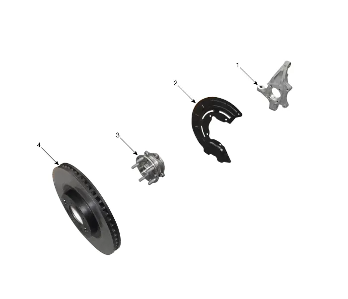
| 1. Knuckle 2. Dust cover |
3. Hub
assembly 4. Brake disc |
Repair procedures
| Removal |
| 1. |
Loosen the wheel nuts slightly.
Raise the vehicle, and make sure it is securely supported.
|
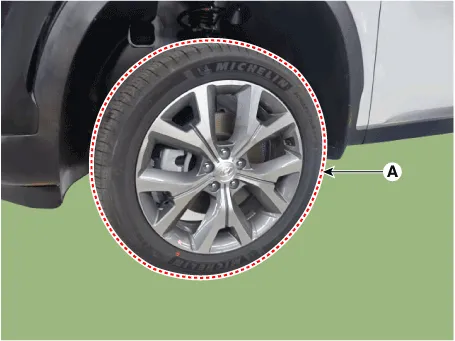
| 2. |
Remove the front wheel and tire (A) from the front hub.
|

| 3. |
Remove the front brake caliper.
(Refer to Brake System - "Front Disc Brake")
|
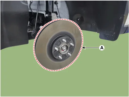
| 4. |
Loosen the screw and then remove the front disc (A).
|
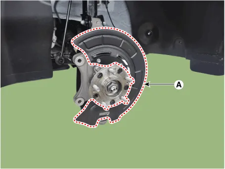
| 5. |
Remove the dust cover (A).
|
| 6. |
Loosen the bolt and then remove the wheel speed sensor (A).
|
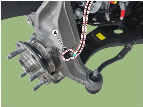
| 7. |
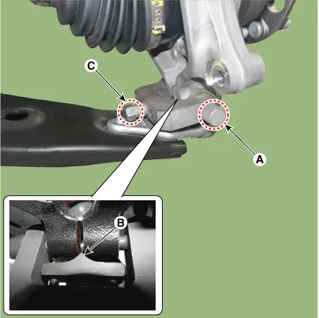
Remove the tie rod end ball joint.
|
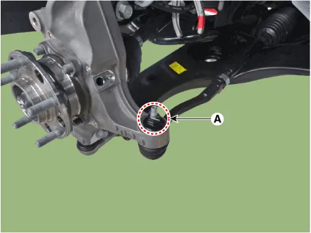
| 8. |
Remove the split pin and nut (A).
|
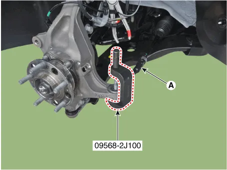
| 9. |
Remove the lower arm from the knuckle by using the SST (09568-4R100).
|
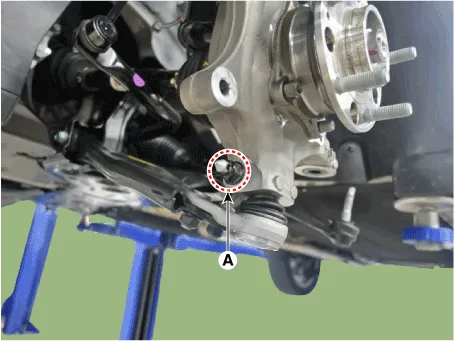
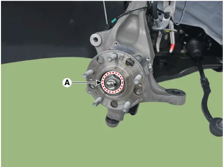
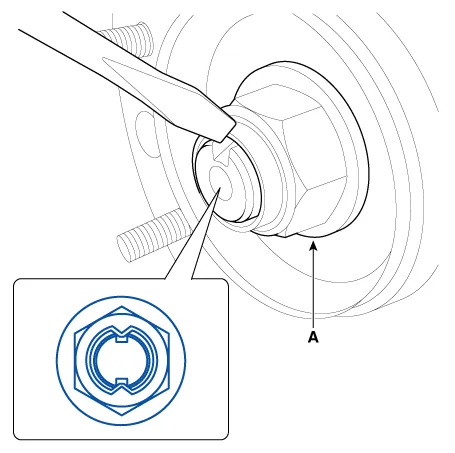
| 10. |
Loosen the driveshaft caulking nut (A).
|

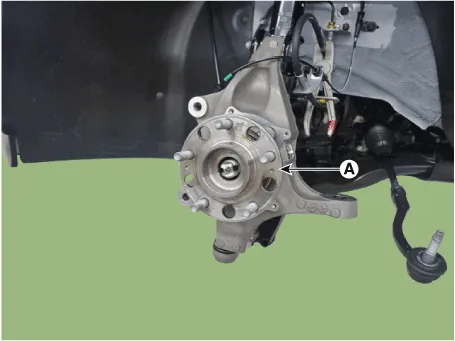
| 11. |
Remove the hub bearing (A) from the front knuckle.
|
| 12. |
Loosen the strut mounting bolts, nuts and then remove the knuckle assembly
(A).
|

| Inspection |
| 1. |
Check the hub for cracks and the splines for wear.
|
| 2. |
Check the brake disc for scoring and damage.
|
| 3. |
Check the knuckle for cracks.
|
| 4. |
Check the bearing for cracks or damage.
|
| Installation |
| 1. |
Install in the reverse order of removal.
|
| 2. |
Check the alignment.
(Refer to Suspension System - "Alingment")
|
Other information:
Hyundai Palisade (LX2) 2020-2026 Service Manual: Rear Temperature Control Actuator
Repair procedures Replacement 1. Disconnect the negative (-) battery terminal. 2. Remove the luggage side trim (Refer to Body - "Luggage Side Trim ") 3. Separate the rear temperature actuator connector (A), loosen the mounting screws a
Hyundai Palisade (LX2) 2020-2026 Service Manual: Description and operation
Description The cruise control system is engaged by the cruise "ON/OFF" main switch located on right of steering wheel column. The system has the capability to cruise, coast, accelerate and resume speed. It also has a safety interrupt, engaged upon depressing brake or shifting select lever.
Categories
- Manuals Home
- Hyundai Palisade Owners Manual
- Hyundai Palisade Service Manual
- Electrochromatic Mirror (ECM) with homelink system
- How to reset the power liftgate
- Resetting the Driver's Seat Memory System
- New on site
- Most important about car

Copyright © 2026 www.hpalisadelx.com - 0.0169