Hyundai Palisade (LX2): ESP(Electronic Stability Program) System / ESP Control Module
Components and components location
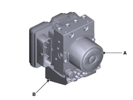
| Components |
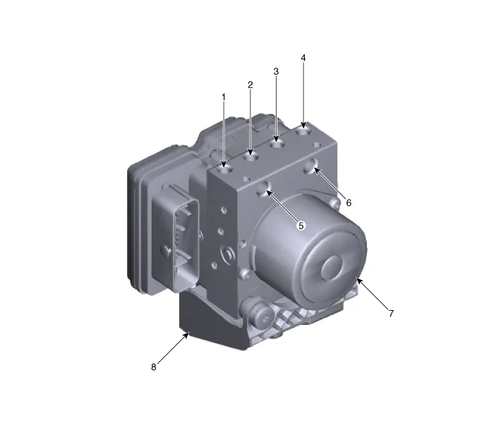
| 1. Front - right (FR) 2. Rear - left (RL) 3. Rear - right (RR) 4. Front - left (FL) |
5. MC2 6. MC1 7. ESP control module (HECU) 8. Bracket |
Repair procedures
| Removal |
| 1. |
Turn ignition switch OFF and disconnect the negative (-) battery cable.
|
| 2. |
In the case of G 3.5 MPI, G3.8 GDI vehicle, removing the variable intake
solenoid (VIS) actuator.
(Refer to Engine Mechanical System - "Variable Intake Solenoid (VIS)
Actuator")
|
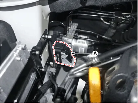
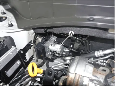
| 3. |
Pull up the lock of the HECU connector and then disconnect the connector
(A).
|
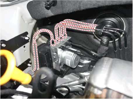
| 4. |
Separate the brake tubes from the HECU by unlocking the nuts (6-ea)
couterclockwise using a spanner.
|
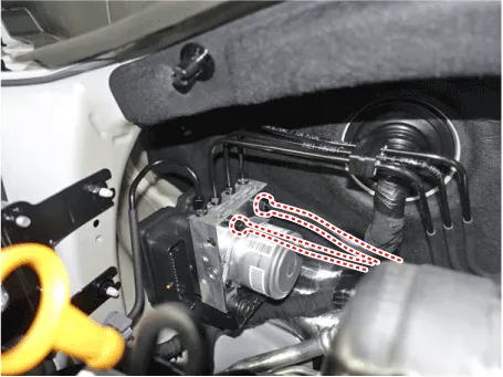
| 5. |
Loosen the ESP control module mounting nut (A) and then remove the ESP
control module from the vehicle.
|
| 6. |
Separate the bracket (B) after remove the mounting bolt from the HECU
(A).
|
| Installation |
| 1. |
To install, reverse the removal procedure.
|
| 2. |
After installation, bleed the brake system.
(Refer to ESP(Electronic Stability Program) System - "ESP System Bleeding")
|
| 3. |
Connect the GDS to the data link connector located underneath the dash
panel.
|
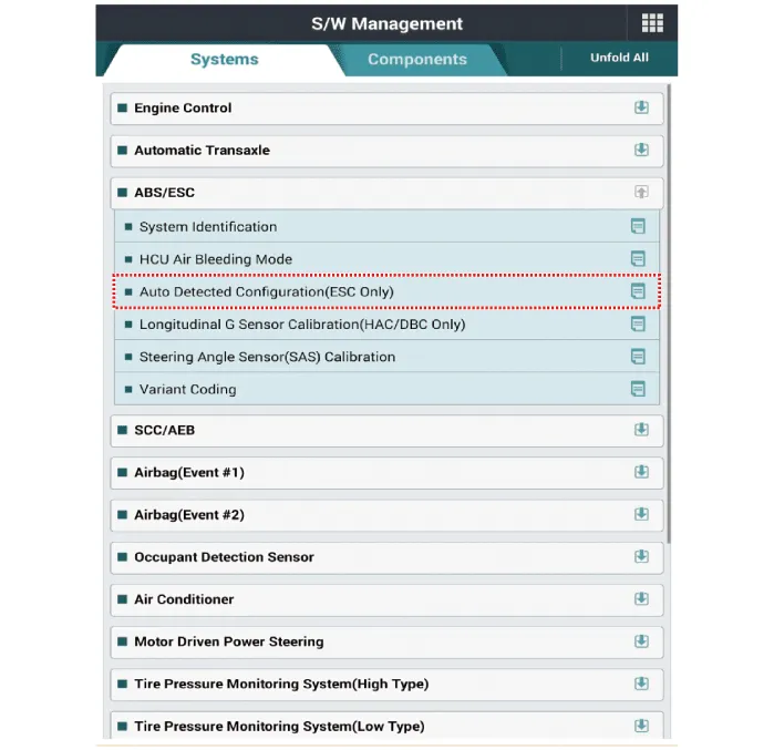
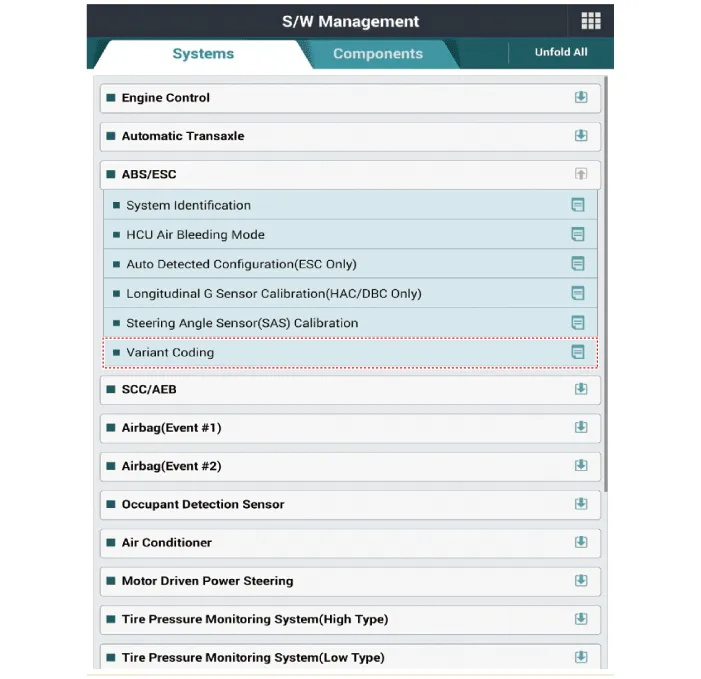
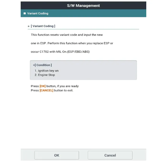
| 4. |
Conduct the Variant coding.
|
| 5. |
Conduct the Auto Detected Sensor Calibration.
|
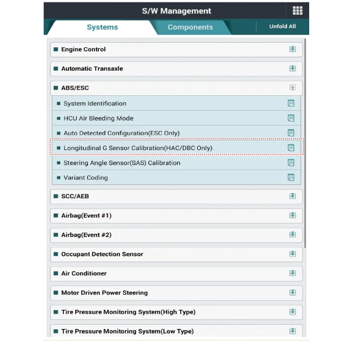
| 6. |
Conduct the Longitudinal G Sensor Calibration.
|
| 7. |
After replacing the ESP control module execute the "Assembly Check (ECU
replacement)" of the additional function to check that the mounting
is successful.
|
| Adjustment |
| 1. |
Connect self-diagnosis connector (16pins) located under the driver side
crash pad to self-diagnosis device, and then turn the self-diagnosis
device after key is ON.
|
| 2. |
Select the "vehicle model" and "ESP/ESC" on GDS vehicle selection screen,
then select OK.
[Variant Code Reset]
[Variant Coding]
[Longitudinal G Sensor Calibration]
Assembly Check (ECU replacement)
|

Failure Diagnosis 1. In principle, ESP and TCS controls are prohibited in case of ABS failure. 2. When ESP or TCS fails, only the failed system control is prohibited.
Description and operation Description 1. The ESP OFF switch is for the user to turn off the ESP system. 2.
Other information:
Hyundai Palisade (LX2) 2020-2026 Service Manual: In-car Sensor
Description and operation Description The In-car air temperature sensor is built in the heater & A/C control unit. The sensor consists of a thermistor that measures the inside temperature. The signal decided by the resistance value that changes in accordance with perceived inside temperature, is delivered to heater co
Hyundai Palisade (LX2) 2020-2026 Service Manual: Intake Actuator
Description and operation Description The intake actuator is located at the blower unit. It regulates the intake door by a signal from the control unit. Pressing the intake selection switch will shift between recirculation and fresh air modes.
Categories
- Manuals Home
- Hyundai Palisade Owners Manual
- Hyundai Palisade Service Manual
- Power Outlet
- Removing and Storing the Spare Tire
- Components and components location
- New on site
- Most important about car
