Hyundai Palisade (LX2): Air conditioning System / Compressor
Description and operation
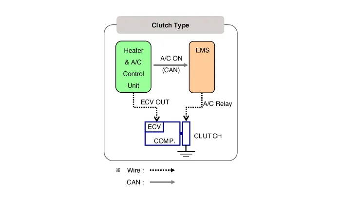
| Description |
Components and components location
| Components |
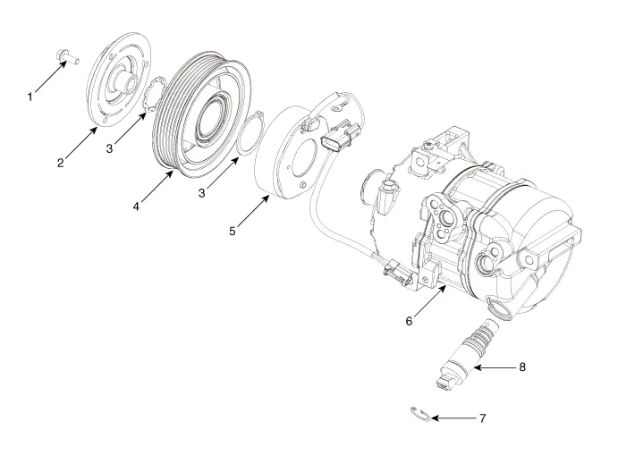
| 1. Clutch bolt 2. Disc & Hub assembly 3. Snap ring 4. Pulley |
5. Clutch magnetic coil 6. Compressor 7. ECV Snap ring 8. Electric Control Valve (ECV) |
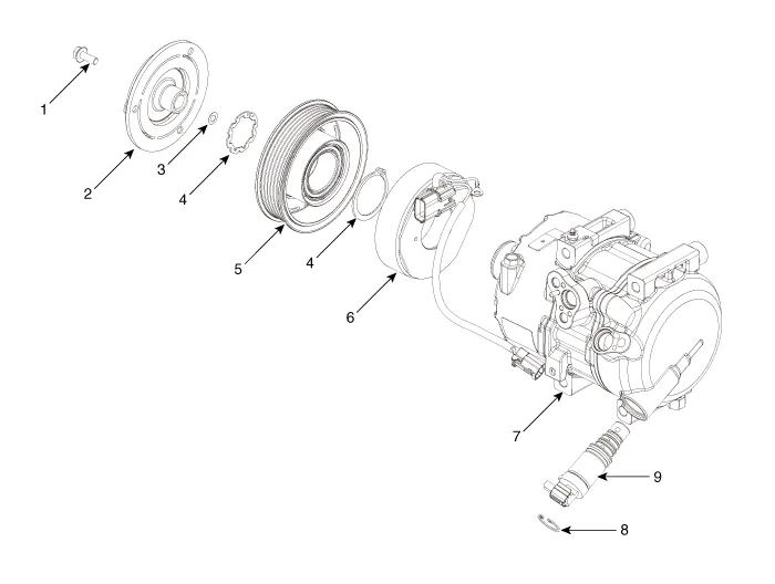
| 1. Clutch bolt 2. Disc & Hub assembly 3. Clutch hub spacer 4. Snap ring 5. Pulley |
6. Clutch magnetic coil 7. Compressor 8. ECV Snap ring 9. Electric Control Valve (ECV) |
Repair procedures
| Removal |
| 1. |
If a compressor is available, the air conditioner is operated for a
few minutes in the engine idle state and then the engine is stopped.
|
| 2. |
Disconnect the negative (-) battery terminal.
|
| 3. |
Recover the refrigerant with a recovery/charging station.
|
| 4. |
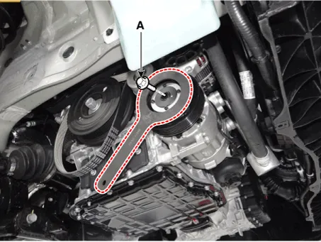
Loosen the drive belt.
(Refer to Engine Mechanical System - "Drive Belt")
|
| 5. |
Loosen the mounting nuts and separate the suction line (A), discharge
line (B).
|


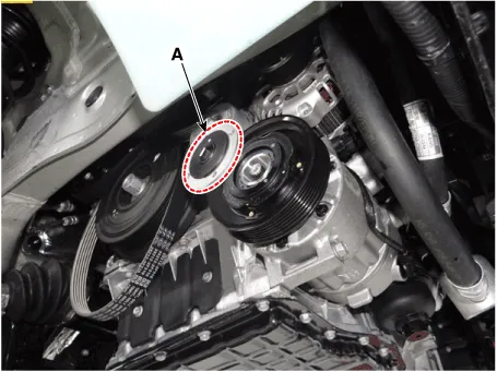
| 6. |
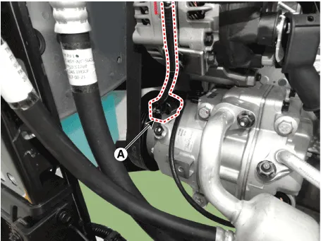
Press the lock pin and separate the ECV connector (A).
|
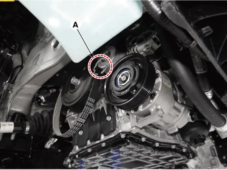
| 7. |
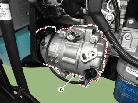
Loosen the mounting bolts and remove the compressor assembly (A).
|
| Installation |
| 1. |
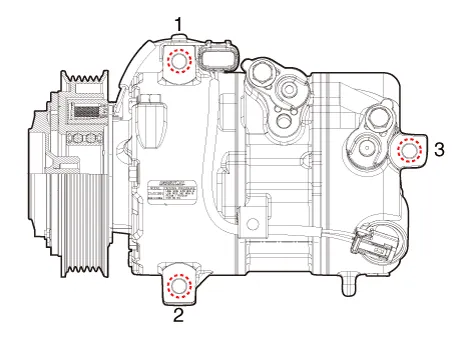
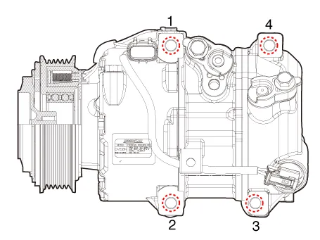
Make sure that the compressor (A) mounting bolt of the correct length
is screwed in. Tighten the mounting bolts in the specified tightening
order.
[R Engine]
[LAMDA Engine]
|
| 2. |
Install in the reverse order of removal.
|
| Inspection |
| 1. |
Check the plated parts of the limiter & hub assembly for color changes,
peeling or other damage. If there is damage, replace the assembly.
|
| 2. |
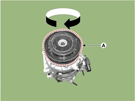
Check the pulley (A) bearing play and drag by rotating the pulley by
hand. Replace the pulley with a new one if it is noisy or has excessive
play / drag.
|
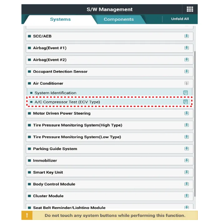
| External Control Valve Compressor Inspection (GDS) |
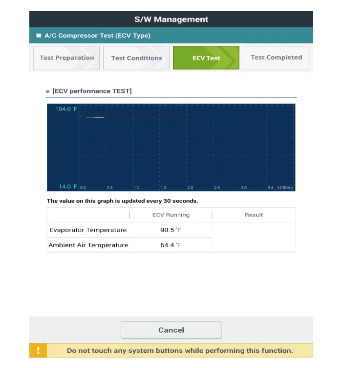
| 1. |
Connect GDS to the vehicle and select 'Aircon Compressor Test(ECV type)'
[ECV1]
|
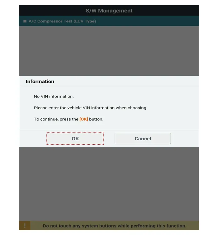
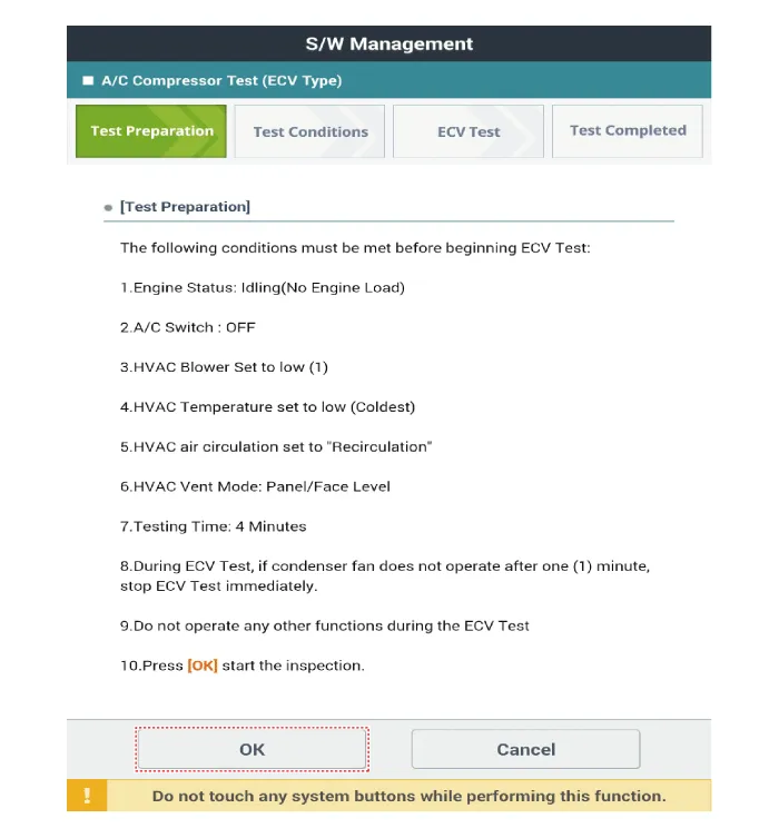
| 2. |
Make the vehicle ready as the GDS instruction on the monitor. (Turn
off A/C 'switch' only)
|

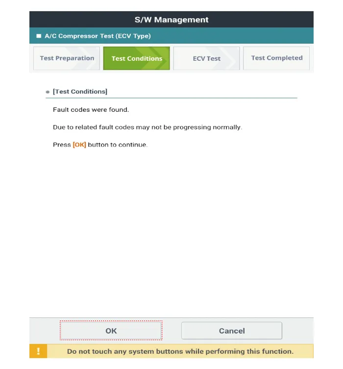
| 3. |
Check if other DTC codes are found before inspect ECV compressor. If
so, solve that problems first. If not, press 'OK' button to continue.
|

| 4. |
Start inspection
|


| 5. |
Check the result of inspection.
[ECV7]
[ECV8]
|
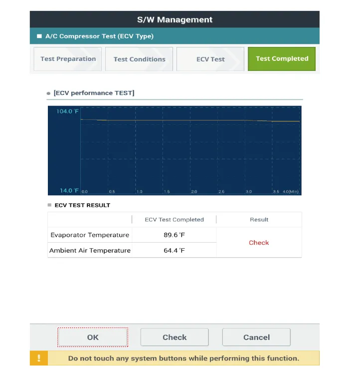
| 6. |
If the result shows "Check" , click "Check" and follow the instruction.
|
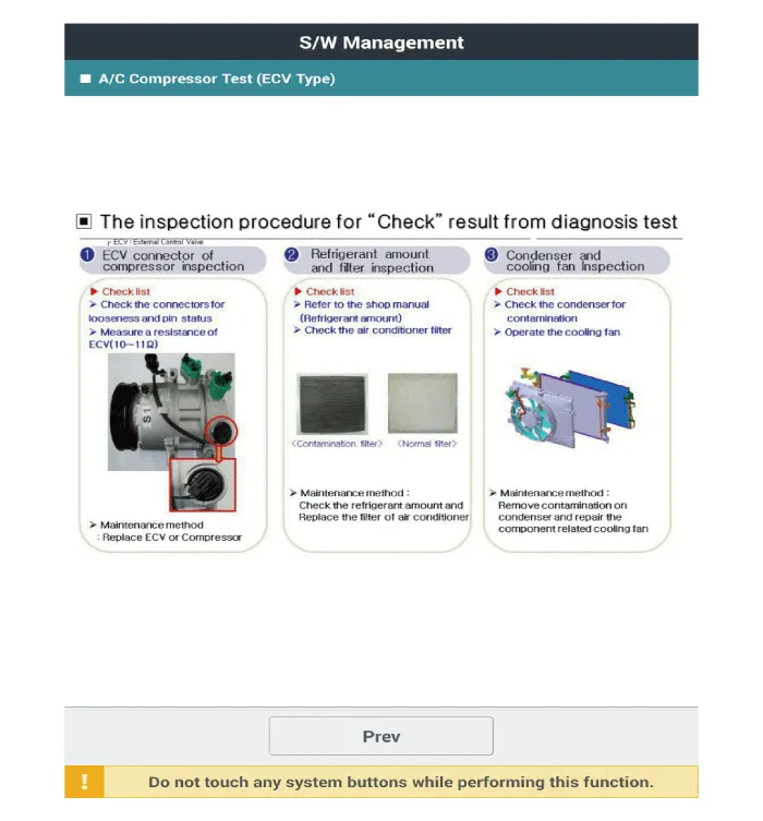
| 7. |
Inspect ECV again from the first step.
|
| Disassembly |
| 1. |
Remove the front tire [RH].
|
| 2. |
Loosen the drive belt.
(Refer to Engine Mechanical System - "Drive Belt")
|
| 3. |
Remove the clutch bolt (A) while holding the pulley with a clutch bolt
remover (09977-3R000).
|
| 4. |
Loossen the limiter bolts and then remove the limiter & hub assembly.
|
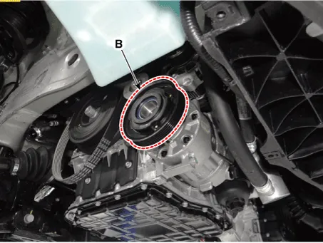
| 5. |
Remove the pulley (B) after removing the snap ring (A) with a snap ring
plier.
|

| 6. |
Reassemble in the reverse order of disassembly.
|

Components and components location Components [Isometric view] 1. Front suction & Liquid pipe assembly [Top view] 1.
Components and components location Components Location 1. Condensor
Other information:
Hyundai Palisade (LX2) 2020-2026 Service Manual: Cluster Ionizer
Description and operation Description The cluster ionizer makes disinfection and decomposition of bad smell from the air-conditioner or inflow air. And it cleans the inside air of a vehicle. When the ignition switch is ON, the ionizer runs "CLEAN" mode and then "ION" mode, switching between both modes.
Hyundai Palisade (LX2) 2020-2026 Service Manual: Surround View Monitor (SVM) Unit
Components and components location Components No Connector A 1 ACC 2 LED 3 EXT Ground 4 Y Shield 5 - 6 C-CAN Low 7
Categories
- Manuals Home
- Hyundai Palisade Owners Manual
- Hyundai Palisade Service Manual
- Convenient Features of Your Vehicle
- Resetting the Driver's Seat Memory System
- Automatic Transaxle System (A8LF1)
- New on site
- Most important about car
