Hyundai Palisade (LX2): Heater / Auto Defogging Actuator
Hyundai Palisade (LX2) 2020-2026 Service Manual / Heating,Ventilation And Air Conditioning / Heater / Auto Defogging Actuator
Description and operation
| Description |
The auto defogging sensor is installed on the front window glass. The sensor
judges and sends signal if moisture occurs to blow out wind for defogging. The
air conditioner control module receives a signal from the sensor and restrains
moisture and eliminates defog by the intake actuator, A/C, auto defogging actuator,
blower motor rpm and mode actuator.
Components and components location
| Components Location |
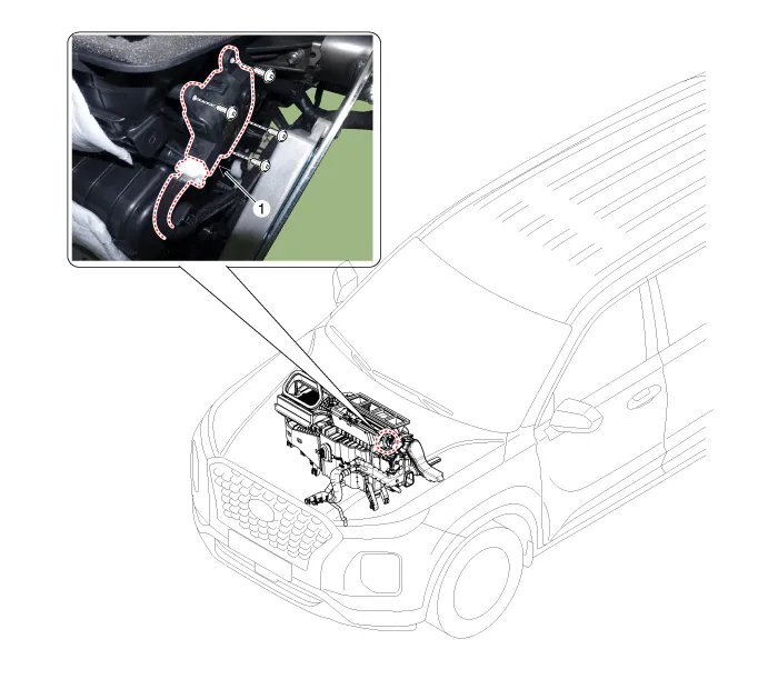
| 1. Auto defogging actuator |
Repair procedures
| Inspection |
| 1. |
Turn the ignition switch OFF.
|
| 2. |
Disconnect the auto defogging connector.
|
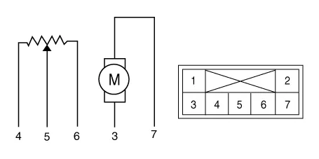
| 3. |
Verify that the auto defogging actuator operates to the open position
when connecting 12V to terminal 3 and grounding terminal 6.
Verify that the auto defogging actuator operates to the close position
when connected in reverse.
|
| 4. |
Connect the auto defogging actuator connector.
|
| 5. |
Turn the ignition switch ON.
|
| 6. |
Check the voltage between terminals 5 and 4.
Specification
|

| 7. |
If the measured voltage is not within specification, check the operation
by replacing the existing auto defogging actuator with a new genuine
part. After that, determine whether replacement of the auto defogging
actuator is required or not.
|
| Replacement |
| 1. |
Disconnect the negative (-) battery terminal.
|
| 2. |
Remove the main crash pad assembly.
(Refer to Body - "Main Crash Pad Assembly")
|
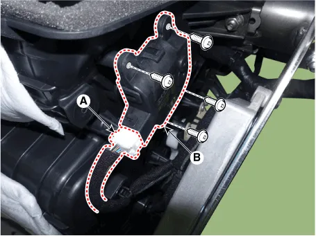
| 3. |
Press the lock pin and separate the connector (A) and loosen the mounting
screws and remove the auto defogging actuator (B).
|
| 4. |
Install in the reverse order of removal.
|
Description and operation Description The mode control actuator is located at the heater unit. It adjusts the position of the mode door by operating the mode control actuator based on the signal of the A/C control unit.
Other information:
Hyundai Palisade (LX2) 2020-2026 Service Manual: Specifications
Specification Air Conditioner Item Specification Compressor Type 7VSX18 (External Variable Displacement Swash Plate) Oil type & Capacity PAG 180 ± 10cc (6.
Hyundai Palisade (LX2) 2020-2026 Service Manual: Components and components location
Categories
- Manuals Home
- Hyundai Palisade Owners Manual
- Hyundai Palisade Service Manual
- General Tightening Torque Table
- Lift and Support Points
- Power Outlet
- New on site
- Most important about car

Copyright © 2026 www.hpalisadelx.com - 0.0175