Hyundai Palisade (LX2): Indicators And Gauges / Components and components location
| Components |
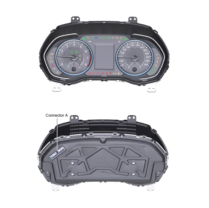
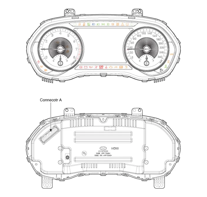
|
No |
Connector A |
No |
Connector B |
|
1 |
Ground |
21 |
Trip switch (-) |
|
2 |
Illumination (-) |
22 |
Trip switch 1 (+) |
|
3 |
Rheostat switch (Down)_Input |
23 |
Trip switch 2 (+) |
|
4 |
Rheostat switch (Up)_Input |
24 |
Active ECO_input switch/ R switch(M/T)_input |
|
5 |
Dentent |
25 |
Driver mode switch/ N switch(M/T)_input |
|
6 |
- |
26 |
Speaker1 (+)_Output |
|
7 |
- |
27 |
Speaker1 (-)_Output |
|
8 |
- |
28 |
- |
|
9 |
- |
29 |
B-CAN (Low) |
|
10 |
- |
30 |
B-CAN (High) |
|
11 |
- |
31 |
Engine Run State_Output |
|
12 |
Vehicle speed_Output |
32 |
C-CAN (High) |
|
13 |
Alternator_Input |
33 |
C-CAN (Low) |
|
14 |
Fuel sender (+)_Input |
34 |
Temperature_Input |
|
15 |
- |
35 |
- |
|
16 |
Fuel sender (-)_Input |
36 |
Steering wheel heater indicator |
|
17 |
Water separate_Input |
37 |
Ground |
|
18 |
Airbag (+)_Input |
38 |
- |
|
19 |
Oil press switch (-)_Input |
39 |
IGN 1 |
|
20 |
- |
40 |
Battery (+) |
Description Communication Network Diagram Abbreviation Explanation IBU Interated Body Control Unit DDM Driver Door Module PTGM Power Tail Gate Module ICU Interated Control Unit ECU Engine Control Unit CLU Cluster MDPS Moter Driven Power Steering SVM Sorround View Monitor ACU Airbag Control Unit VDC Vehicle Dynamic Control SCC Smart Cruise Control LKA Lane Keeping Assist BCW Blind-Spot Collision Warning SAS Steering Angle Sensor HUD Head up Display TCU Transmission Control Unit FR DATC Dual Automatic Temp Control 4WD Four Wheel Drive F/PUMP Fuel Pump Control Module POCS Passenger Occupant Classification System IMS Integrated Memory System AMP Amplifier AVN Head Unit (Audio / AVN) HUD Head Up Display RR CAMERA Rrar View Camera FR CON Front Console Switch EOP Electric Oil Pump SBW Shift BY Wire W/CHAR Wireless Power Chager FR M/LP Front Mood Lamp 3ND FOLD 3ND Seat Folding Control Unit AUDIO Audio unit KEY BOARD Center Fascia Keyboard
Other information:
Hyundai Palisade (LX2) 2020-2026 Service Manual: Troubleshooting
Troubleshooting Problem Symptoms Table Before replacing or repairing air conditioning components, first determine if the malfunction is due to the refrigerant charge, air flow or compressor. Use the table below to help you find the cause of the problem.
Hyundai Palisade (LX2) 2020-2026 Service Manual: Description and operation
Description Surround View Monitor (SVM) is the system that allows video monitoring of 360 degrees around the vehicle. The system includes 4 ultra optical camera mounted around the vehicle (front, both sides, rear). The video from these cameras are applied with distortion compensation, time point conversion, and video me
Categories
- Manuals Home
- Hyundai Palisade Owners Manual
- Hyundai Palisade Service Manual
- Automatic Transaxle System (A8LF1)
- Components and components location
- How to reset the power liftgate
- New on site
- Most important about car
