Hyundai Palisade (LX2): Seat Electrical / Lumber Support System
Repair procedures
| Removal |
| 1. |
Disconnect the negative (-) battery terminal.
|
| 2. |
Remove the front seat back cover.
(Refer to Body - "Front Seat Back Cover")
|
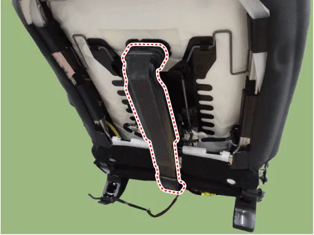
| 3. |
Remove the air duct.
|
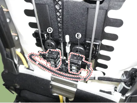
| 4. |
Disconnect the lumber support motor connector (D) & (E).
|
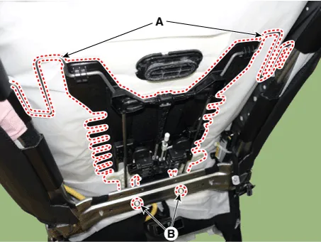
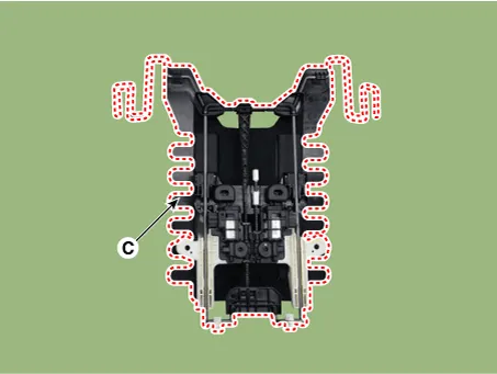
| 5. |
Remove the lumber support assembly (C) after removing the rod (A) &
mounting fasner (B).
|
| Installation |
| 1. |
Install the lumber support assembly.
|
| 2. |
Install the seat back cover.
|
| 3. |
Install the front seat assembly.
|
Repair procedures Removal 1. Disconnect the negative (-) battery terminal. 2. Remove the front seat shield outer cover.
Components and components location Components 1. Front seat heater switch 2. Rear seat heater switch Schematic diagrams Circuit Diagram Front Seat No Connector A 1 C_CAN (High) 2 C_CAN (Low) 3 - 4 LIN 5 - 6 Auto hold signal 7 - 8 Battery (+) 9 IGN 10 Illumination (+) 11 - 12 Illumination (-) 13 Ground 14 DETENT 15 - 16 PDW signal 17 Steering wheel heater signal 18 DBC signal 19 ISG signal 20 SVM/RVM signal 21 ISG indicator 22 SVM indicator 23 PDW indicator 24 Steering whell heater indicator 2nd Seat No Connector A 1 Battery (+) 2 ISG Power(+) 3 Illumination (+) 4 Sensor REF (+5V) 5 Mode actuator feadback 6 Temperature actuator feedback 7 Mode actuator (Vent) 8 Mode actuator (Defrost) 9 Temperature actuator (Cooling) 10 Temperature actuator (Heating) 11 DETENT (-) 12 K-LINE 13 LIN line (Rear left seat) 14 LIN line (Rear right seat 15 - 16 Illumination (-) 17 IGN 2 18 IGN 1 19 Blower motor (+) 20 - 21 Rear FET (Drain feedback) 22 Rear FET (Gate) 23 Left heater swtich 24 Left heater indicator (High) 25 Left heater indicator (Middle) 26 Left heater indicator (Low) 27 Right heater swtich 28 Right heater indicator (High) 29 Right heater indicator (Middle) 30 Right heater indicator (Low) 31 Sensor ground 32 Ground Repair procedures Removal Front seat 1.
Other information:
Hyundai Palisade (LX2) 2020-2026 Service Manual: PTC Heater (Diesel only)
Description and operation Description The PTC (Positive Temperature Coefficient) heater is installed at the exit or the backside of the heater core. The PTC heater is an electric heater using a PTC element as an auxiliary heating device that supplements deficiency of interior heat source in highly effective diesel engi
Hyundai Palisade (LX2) 2020-2026 Service Manual: Schematic diagrams
System Block Diagram Component Parts And Function Outline Component part Function Vehicle-speed sensor, ESP/ABS Control Module Converts vehicle speed to pulse. ECM Receives signals from sensor and control switches.
Categories
- Manuals Home
- Hyundai Palisade Owners Manual
- Hyundai Palisade Service Manual
- Electronic Child Safety Lock System
- Automatic Transaxle Fluid (ATF)
- Emergency liftgate safety release
- New on site
- Most important about car
