Hyundai Palisade (LX2): Seat Electrical / Seat Heater Switch
Components and components location
| Components |
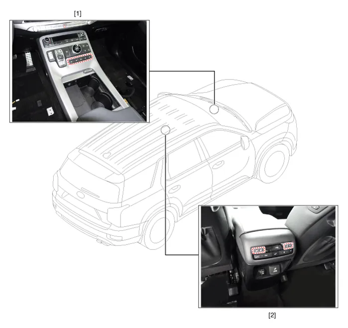
| 1. Front seat heater switch |
2. Rear seat heater switch |
Schematic diagrams
| Circuit Diagram |
|
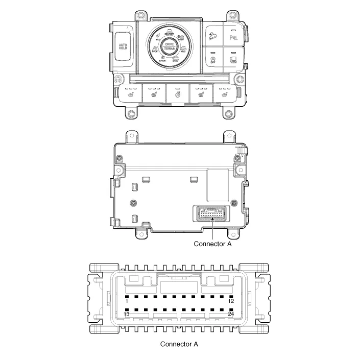
No |
Connector A |
|
1 |
C_CAN (High) |
|
2 |
C_CAN (Low) |
|
3 |
- |
|
4 |
LIN |
|
5 |
- |
|
6 |
Auto hold signal |
|
7 |
- |
|
8 |
Battery (+) |
|
9 |
IGN |
|
10 |
Illumination (+) |
|
11 |
- |
|
12 |
Illumination (-) |
|
13 |
Ground |
|
14 |
DETENT |
|
15 |
- |
|
16 |
PDW signal |
|
17 |
Steering wheel heater signal |
|
18 |
DBC signal |
|
19 |
ISG signal |
|
20 |
SVM/RVM signal |
|
21 |
ISG indicator |
|
22 |
SVM indicator |
|
23 |
PDW indicator |
|
24 |
Steering whell heater indicator |
|
No |
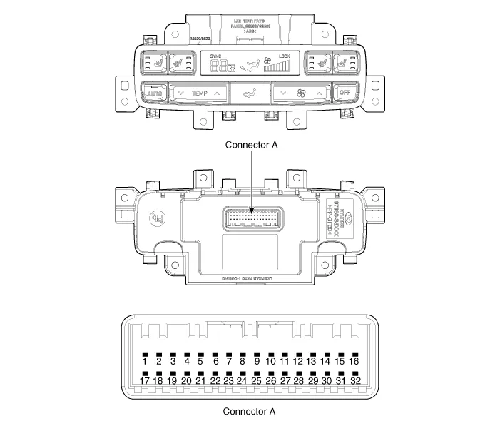
Connector A |
|
1 |
Battery (+) |
|
2 |
ISG Power(+) |
|
3 |
Illumination (+) |
|
4 |
Sensor REF (+5V) |
|
5 |
Mode actuator feadback |
|
6 |
Temperature actuator feedback |
|
7 |
Mode actuator (Vent) |
|
8 |
Mode actuator (Defrost) |
|
9 |
Temperature actuator (Cooling) |
|
10 |
Temperature actuator (Heating) |
|
11 |
DETENT (-) |
|
12 |
K-LINE |
|
13 |
LIN line (Rear left seat) |
|
14 |
LIN line (Rear right seat |
|
15 |
- |
|
16 |
Illumination (-) |
|
17 |
IGN 2 |
|
18 |
IGN 1 |
|
19 |
Blower motor (+) |
|
20 |
- |
|
21 |
Rear FET (Drain feedback) |
|
22 |
Rear FET (Gate) |
|
23 |
Left heater swtich |
|
24 |
Left heater indicator (High) |
|
25 |
Left heater indicator (Middle) |
|
26 |
Left heater indicator (Low) |
|
27 |
Right heater swtich |
|
28 |
Right heater indicator (High) |
|
29 |
Right heater indicator (Middle) |
|
30 |
Right heater indicator (Low) |
|
31 |
Sensor ground |
|
32 |
Ground |
Repair procedures
| Removal |
| 1. |
Disconnect the negative (-) batttery terminal.
|
| 2. |
Remove the floor console upper cover assembly.
(Refer to Body - "Floor Console Assembly")
|
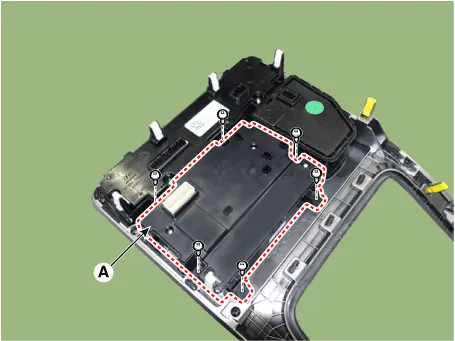
| 3. |
Remove the seat heater switch (A).
|
| 1. |
Disconnect the negative (-) batttery terminal.
|
| 2. |
Remove the Rear A/C & Heater control unit.
(Refer to Heating, Ventilation and Air Conditioning - "Heater & A/C
Control Unit (Rear)")
|
| Installation |
| 1. |
Connect the seat heater switch connector.
|
| 2. |
Install the console upper switch assembly.
|
| 3. |
Connect the negative (-) batttery terminal.
|
| 1. |
Install the Rear A/C & Heater control unit.
|
| 2. |
Connect the negative (-) batttery terminal.
|
Repair procedures Removal 1. Disconnect the negative (-) battery terminal. 2. Remove the front seat back cover.
Components and components location Components Driver/Passenger Seat Heater 1. Seat cushion heater 2. Seat heater unit (Passenger only) 3.
Other information:
Hyundai Palisade (LX2) 2020-2026 Service Manual: PTC Heater (Diesel only)
Description and operation Description The PTC (Positive Temperature Coefficient) heater is installed at the exit or the backside of the heater core. The PTC heater is an electric heater using a PTC element as an auxiliary heating device that supplements deficiency of interior heat source in highly effective diesel engi
Hyundai Palisade (LX2) 2020-2026 Service Manual: General safety information and caution
General Safety Information and Caution 1. Be careful when driving the vehicle using the smart cruise control system as follows. (1) On curves or inclines/declines • The smart cruise control system may have limits to detect
Categories
- Manuals Home
- Hyundai Palisade Owners Manual
- Hyundai Palisade Service Manual
- Electronic Child Safety Lock System
- Components and components location
- General Tightening Torque Table
- New on site
- Most important about car
