Hyundai Palisade: Intake And Exhaust System / Intake Manifold
Hyundai Palisade (LX2) 2020-2025 Service Manual / Engine Mechanical System / Intake And Exhaust System / Intake Manifold
Components and components location
| Components |
| 1. Intake manifold |
2. Intake manifold gasket |
Repair procedures
| Removal and Installation |
| 1. |
Remove the engine cover.
(Refer to Engine and Transaxle Assembly - "Engine Cover")
|
| 2. |
Remove the air cleaner assembly.
(Refer to Intake And Exhaust System - "Air Cleaner")
|
| 3. |
Remove the surge tank.
(Refer to Intake And Exhaust System - "Surge Tank")
|
| 4. |
Remove the low pressure fuel line mounting bolts (A).
|
| 5. |
Remove the intake manifold (A).
|

| 6. |
Install in the reverse order of removal.
|

 Variable Intake Solenoid (VIS) Actuator
Repair procedures
Removal and Installation
VIS 1 [Intake Manifold]
1.
Disconnect the battery negative terminal.
2...
 Exhaust Manifold
Components and components location
Components
1. LH Exhaust manifold gasket
2. LH Exhaust manifold
3. LH Heat protector
4...
Other information:
Hyundai Palisade (LX2) 2020-2025 Service Manual: Fuel Tank Air Filter
Repair procedures Removal 1. Switch "OFF" the ignition and disconnect the negative (-) battery terminal. 2. Disconnect the vent hose quick-connector (B), the vapor hose quick-connector (A) from the canister...
Hyundai Palisade (LX2) 2020-2025 Service Manual: Cylinder Head
Components and components location Components 1. RH intake camshaft OCV 2. Camshaft thrust bearing cap 3. Camshaft bearing cap 4. RH exhaust camshaft 5. RH intake camshaft 6. RH exhaust camshaft CVVT assembly 7...
Categories
- Manuals Home
- 1st Generation Palisade Owners Manual
- 1st Generation Palisade Service Manual
- AWD Operation
- Reverse Parking Aid Function
- Theft-alarm system
- New on site
- Most important about car
How Does the Air Bag System Operate?
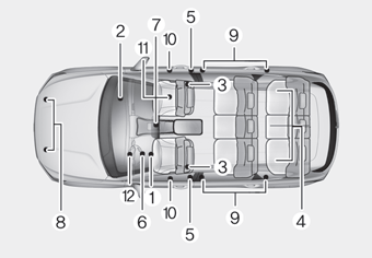
The SRS consists of the following components:
1. Driver's front air bag module
2. Passenger's front air bag module
3. Side air bag modules
4. Curtain air bag modules
5. Retractor pre-tensioner
6. Air bag warning light
7. SRS control module (SRSCM)/
Rollover sensor
8. Front impact sensors
9. Side impact sensors
10.Side pressure sensors
11. Occupant classification system
12. Driver’s knee airbag module

Copyright © 2025 www.hpalisadelx.com