Hyundai Palisade (LX2): Integrated Body Control Unit (IBU) / IMS (Integrated Memory System) module
Hyundai Palisade (LX2) 2020-2026 Service Manual / Body Electrical System / Integrated Body Control Unit (IBU) / IMS (Integrated Memory System) module
Components and components location
| Components |

IMS input/output pin information
|
No |
Connector A |
Connector B |
Connector C |
|
1 |
Cushion extension moter (Front) |
B+ (Power) |
Seat slide motor switch (Front) |
|
2 |
Seat recline motor (Front) |
Ground (Power) |
Seat recline switch (Front) |
|
3 |
Seat height motor (Up) |
B+ (Power) |
Seat tilt switch (Up) |
|
4 |
Seat slide motor(Front) |
- |
Seat height switch (Up) |
|
5 |
Seat Cushion extension moter (Rear) |
Ground |
Seat cushion extension switch (Front) |
|
6 |
Seat recline motor (Rear) |
|
B_CAN (High) |
|
7 |
Seat tilt motor (Up) |
B_CAN (Low) |
|
|
8 |
Seat tilt motor (Down) |
Lumber motor (Up) |
|
|
9 |
Seat height motor (Down) |
Lumber motor (Down) |
|
|
10 |
Seat slide motor (Rear) |
Seat slide sensor |
|
|
11 |
|
Seat tilt sensor |
|
|
12 |
- |
||
|
13 |
Seat position sensor power |
||
|
14 |
IGN 1 |
||
|
15 |
Seat slide switch (Rear) |
||
|
16 |
Seat recline switch (Rear) |
||
|
17 |
Seat tilt switch (Down) |
||
|
18 |
Seat height switch (Down) |
||
|
19 |
Seat cushion extension switch (Rear) |
||
|
20 |
Ground |
||
|
21 |
Lumber motor (Low) |
||
|
22 |
IMS switch 2 |
||
|
23 |
- |
||
|
24 |
Seat recline sensor |
||
|
25 |
Seat height sensor |
||
|
26 |
- |
||
|
27 |
- |
||
|
28 |
Battery (+) |
Repair procedures
| Removal |
| 1. |
Remove the negative (-) battery terminal.
|
| 2. |
Remove the front seat assembly.
(Refer to Body - "Front Seat Assembly")
|
| 3. |
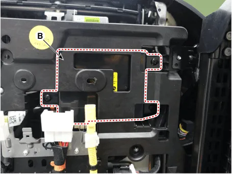
Remove the IMS module (B) after disconnecting the connector and loosening
the screws (3EA).
|
| Installation |
| 1. |
Install the IMS module after reconnecting the connector.
|
| 2. |
Install the driver seat.
|

| 3. |
Connect the negative (-) battery terminal.
|
Specifications Specifications Memory Power Seat Unit Item Specification Rating voltage DC 12V Operation voltage DC 9V - 16V Operation temperaure -30°C to 75°C parastic current Max.
Components and components location Components Repair procedures Inspection 1. Disconnect the IMS control switch connector.
Other information:
Hyundai Palisade (LX2) 2020-2026 Service Manual: Special service tools
Hyundai Palisade (LX2) 2020-2026 Service Manual: Parking/View Switch
Repair procedures Removal 1. Disconnect the negative (-) battery terminal. 2. Remove the floor console upper cover. (Refer to Body - "Floor Console Assembly") 3.
Categories
- Manuals Home
- Hyundai Palisade Owners Manual
- Hyundai Palisade Service Manual
- Resetting the Driver's Seat Memory System
- Body (Interior and Exterior)
- Emergency liftgate safety release
- New on site
- Most important about car

Copyright © 2026 www.hpalisadelx.com - 0.0153